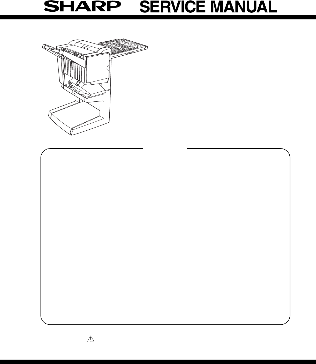
Sharp AR-F14 Dokumentacja Strona 1
Przeglądaj online lub pobierz Dokumentacja dla Kopiarki Sharp AR-F14. Sharp AR-F14 Specifications Instrukcja obsługi
- Strona / 74
- Spis treści
- ROZWIĄZYWANIE PROBLEMÓW
- BOOKMARKI
- FINISHER 1
- PUNCH UNIT 1
- CONTENTS 2
- [1] INTRODUCTION 3
- 1. External view 4
- 2. Internal structure 4
- 5. Puncher section (AR-PN1) 6
- 1.AR-F14 7
- Guide pin 11
- Staple position label 12
- 2. AR-PN1 13
- Top cover 14
- Connect to CN14 on PWB 15
- Jam handling dial 16
- Punch position label 16
- [4] OPERATIONAL DESCRIPTION 17
- PCB(option) 19
- 2. Feed/Drive System 20
- B.Feed/Delivery 21
- C.Job Offset 22
- 3. Stapling Operation 23
- D.Stapler Unit 25
- 4. Delivery Tray Operation 26
- 5. Saddle Unit 27
- C.Paper Feed System 28
- D.Stack Feed System 28
- E.Fold/Delivery System 28
- (2)Paper Folding 29
- Finisher unit control system 30
- (2)Punching Operation 31
- 7. Detecting Jams 32
- Punch controller PCB 34
- (puncher unit; option) 34
- [5] DISASSEMBLY AND ASSEMBLY 35
- (7)Removing the Saddle Guide 36
- (1)Removing the Stapler Unit 37
- (4)Removing the Saddle Unit 40
- (9)Removing the Feed Roller 43
- (11) Removing the Paddle 44
- Maintenance cover 47
- Rear cabinet 47
- (2) Interface transport unit 48
- 2. Puncher Unit (option) 51
- (3)Removing the LED PCB 53
- [6] MAINTENANCE 54
- [7] MACHINE OPERATION 55
- The displayed menu will vary 56
- 12345678 57
- (Input display) 58
- (Execution display) 58
- [9] TROUBLE SHOOTING 59
- 3. Troubleshooting 60
- (6) F1-10, Slide Motor Fault 61
- (8) F1-15, Shift Motor Fault 62
- (9) F1-15, Shift Motor Fault 62
- (10) F1-15, Shift Motor Fault 62
- B. Puncher unit, option 63
- [10] SIMULATIONS 65
- [11] ELECTRICAL SECTION 67
- 2. Wiring diagram (AR-F14) 68
- Finisher controller PCB 69
- Stapler unit 69
- To puncher unit (option) 69
- To Interface transport unit 69
- 3. Wiring diagram (AR-PN1) 70
- Controller PCB 71
- CAUTION FOR BATTERY DISPOSAL 73
- COPYRIGHT 74
- 2004 BY SHARP CORPORATION 74
Podsumowanie treści
This document has been published to be used forafter sales service only.The contents are subject to change without notice.Parts marked with “ “ are im
AR-F14/PN1 UNPACKING AND INSTALLATION 3-4•If the copier is equipped with a small stand and three paper drawers,proceed to step16).•If the copier is eq
AR-F14/PN1 UNPACKING AND INSTALLATION 3-518) Install the stapler unit into the finisher.<1>Remove the packing the tape (two pieces) from the loc
AR-F14/PN1 UNPACKING AND INSTALLATION 3-6<2>If the gap between the copier and the finisher is not uniform atthe upper and lower parts, remove th
AR-F14/PN1 UNPACKING AND INSTALLATION 3-72. AR-PN1<Before installation>For installation of AR-PN1A/PN1B/PN1C/PN1D, a saddle stitch finisher(AR-F
AR-F14/PN1 UNPACKING AND INSTALLATION 3-83) Remove the top cover.<1> Remove the four top cover securing screws and remove the topcover.<2>
AR-F14/PN1 UNPACKING AND INSTALLATION 3-95) Attach the punch module.<1>Insert the two bosses of the punch unit into the boss holes of thefinishe
AR-F14/PN1 UNPACKING AND INSTALLATION 3-10<4>Reattach the jam handling dial and close the front cover.8) Paste the dust box label to the top cov
AR-F14/PN1 OPERATIONAL DESCRIPTION 4-1[4] OPERATIONAL DESCRIPTION1. Basic OperationsA. SpecificationsThe finisher serves to deliver sheets coming from
AR-F14/PN1 OPERATIONAL DESCRIPTION 4-2C. Inputs to and Outputs from the Finisher Controller PCB•Inputs to the Finisher Controller PCB (1/2)Fig.F02-103
AR-F14/PN1 OPERATIONAL DESCRIPTION 4-3•Inputs to and Outputs from the Finisher Controller (1/2)Fig.F02-103-05•Inputs to and Outputs from the Finisher
CONTENTS[1] INTRODUCTION1. Product outline . . . . . . . . . . . . . . . . . . . . . . . . . . . . . . . 1-12. Configuration . . . . . . . . . . . .
AR-F14/PN1 OPERATIONAL DESCRIPTION 4-42. Feed/Drive SystemA. OutlineThe machine performs the following in response to the commandscoming from its host
AR-F14/PN1 OPERATIONAL DESCRIPTION 4-5d.Saddle DeliveryThe machine deposits a stack of sheets on the processing tray, staples it(middle 2-point), and
AR-F14/PN1 OPERATIONAL DESCRIPTION 4-6Fig.F02-202-02Table.T02-202-02C.Job Offset(1)Outline"Job offset" refers to the operation by which the
AR-F14/PN1 OPERATIONAL DESCRIPTION 4-7Offsetting in the backward directionFig.F02-203-04(4)Stack Delivery OperationStack delivery takes place when 10
AR-F14/PN1 OPERATIONAL DESCRIPTION 4-8B.Stapling OperationWhen stacking and alignment of paper on the processing tray arecomplete, the finisher contro
AR-F14/PN1 OPERATIONAL DESCRIPTION 4-9D.Stapler UnitThe staple/fold motor (FFSM) is used to perform stapling operation. Thismotor rotates the cam one
AR-F14/PN1 OPERATIONAL DESCRIPTION 4-10d.Middle 2-point stapling (bind mode)The stapler waits at the back. The stapler moves to and returns from thes
AR-F14/PN1 OPERATIONAL DESCRIPTION 4-115. Saddle UnitA.Basic Operations(1)OutlineThe machine stitches a stack of sheets (middle 2-point), then folds t
AR-F14/PN1 OPERATIONAL DESCRIPTION 4-12d.Folding/deliveryThe paper pushing plate pushes in the center of the paper stack to feed ittoward the paper fo
AR-F14/PN1 OPERATIONAL DESCRIPTION 4-13(2)Paper FoldingPaper is folded using paper fold rollers and a paper pushing plate. Almost concurrently with th
AR-F14/PN1 INTRODUCTION 1-1[1] INTRODUCTION1. Product outlineThis unit is installed to the following machines to perform the after-process of output p
AR-F14/PN1 OPERATIONAL DESCRIPTION 4-146. Puncher Unit (option)A. Basic Operations(1)OutlineThe puncher unit is an option, and is designed for install
AR-F14/PN1 OPERATIONAL DESCRIPTION 4-15(2)Punching OperationThe hole puncher is driven by the punch motor (FPNM). The homeposition for the hole punche
AR-F14/PN1 OPERATIONAL DESCRIPTION 4-16(3)Horizontal Registration OperationThe horizontal registration drive for the punch slide unit is provided byth
AR-F14/PN1 OPERATIONAL DESCRIPTION 4-17(1)Inlet Sensor Delay Jam (1011)The inlet sensor does not detect paper approximately 1.5 sec after the host mac
AR-F14/PN1 OPERATIONAL DESCRIPTION 4-188. Power Supply SystemA.Finisher/Saddle Assembly(1)OutlineWhen the host machine is turned on, it supplies the f
AR-F14/PN1 DISASSEMBLY AND ASSEMBLY 5-1[5] DISASSEMBLY AND ASSEMBLY1. Finisher Saddle UnitA. Externals and ControlsFig.F03-101-01(1)Removing the Deliv
AR-F14/PN1 DISASSEMBLY AND ASSEMBLY 5-23) Remove the screw [4], and detach the processing tray rear cover [5];then, detach the upper.Fig.F03-101-08(5)
AR-F14/PN1 DISASSEMBLY AND ASSEMBLY 5-3NOTE: Be sure to mount the side guide after securely fitting the papersurface detecting lever (rear) [5] in the
AR-F14/PN1 DISASSEMBLY AND ASSEMBLY 5-45) Remove the timing belt [13].6) Remove the E-ring [14] to remove the staple position check gear[15].Fig.F03-1
AR-F14/PN1 DISASSEMBLY AND ASSEMBLY 5-512) Mount the staple position check gear [27] so that the blue mark [25]on the staple position check gear is al
AR-F14/PN1 EXTERNAL VIEWS AND INTERNAL STRUCTURES 2-1[2] EXTERNAL VIEWS AND INTERNAL STRUCTURES1. External view2. Internal structureA. Finisher sectio
AR-F14/PN1 DISASSEMBLY AND ASSEMBLY 5-6(4)Removing the Saddle Unit1) Remove the front cover. (See 1.A.(2).)2) Remove the rear cover. (See 1.A.(3).)3)
AR-F14/PN1 DISASSEMBLY AND ASSEMBLY 5-77) Remove the stop ring [10], and detach the timing belt [11].8) Disconnect the connector [12], and free the ha
AR-F14/PN1 DISASSEMBLY AND ASSEMBLY 5-8(7)Removing the Staple/Fold Drive Unit1) Open the front door [1], and slide out the stapler unit [2] slightly t
AR-F14/PN1 DISASSEMBLY AND ASSEMBLY 5-9(8)Removing the Feed Motor Unit1) Remove the rear cover. (See 1.A.(3).)2) Open the harness retainer [1], and di
AR-F14/PN1 DISASSEMBLY AND ASSEMBLY 5-104) Push up the stack delivery roller (upper) [4] from below to free thestack deliver roller (upper) [4] from t
AR-F14/PN1 DISASSEMBLY AND ASSEMBLY 5-11(12)Removing the Stack delivery roller (lower)/Delivery Belt1) Remove paddle assembly, and separate it from th
AR-F14/PN1 DISASSEMBLY AND ASSEMBLY 5-12C. PCBs(1)Removing the Finisher Controller PCB1) Remove the rear cover. (See 1.A.(3).)2) Disconnect the 17 con
AR-F14/PN1 DISASSEMBLY AND ASSEMBLY 5-13D. Interface transport section (1) Decolor unita. Rear cabinet1) Remove the screw (1 pc), and remove the maint
AR-F14/PN1 DISASSEMBLY AND ASSEMBLY 5-14g. Decolor roller1) Remove the frame unit.2) Remove the E-ring, the gear, and the bearing. Remove the decolorr
AR-F14/PN1 DISASSEMBLY AND ASSEMBLY 5-15e. Interface transport motor1) Remove the connector and the screw, and remove the interfacetransport motor.f.
AR-F14/PN1 EXTERNAL VIEWS AND INTERNAL STRUCTURES 2-23. Finisher and saddle sectionA. SensorFig. F05-201-01 B. Motor and PWBFig. F05-201-02Code Name A
AR-F14/PN1 DISASSEMBLY AND ASSEMBLY 5-167) Remove the E-ring, and remove the interface transport drive rollerunit. Remove the bearing from the interfa
AR-F14/PN1 DISASSEMBLY AND ASSEMBLY 5-172. Puncher Unit (option)A.Puncher Driving System(1)Removing the Punch Motor1) Remove the two screws [1].2) Dis
AR-F14/PN1 DISASSEMBLY AND ASSEMBLY 5-1810)Remove the four screws [14] to remove the upper transmissionsensor unit [15] and lower transmission sensor
AR-F14/PN1 DISASSEMBLY AND ASSEMBLY 5-19(3)Removing the LED PCB1) Remove the waste case.2) Disconnect connector [1].3) Remove the harness [3] from the
AR-F14/PN1 MAINTENANCE 6-1[6] MAINTENANCE1. Maintenance System Table2. Discarding punch waste (when a punch unit is installed)1) Press the detach butt
AR-F14/PN1 MACHINE OPERATION 7-1[7] MACHINE OPERATION1. Staple sort modeCollated sets of printouts are stapled and delivered to the offset tray (upper
AR-F14/PN1 MACHINE OPERATION 7-22. Setup by the printer driverA. Setup procedures when the staple function is used1) Select "PROPERTY" in th
AR-F14/PN1 ADJUSTMENTS 8-1[8] ADJUSTMENTS1. Finisher/saddle unitA. Adjusting the Folding PositionThe folding position is adjusted by matching it with
AR-F14/PN1 ADJUSTMENTS 8-2C. Registering the Number of Punch HolePerform the following to register the type of puncher unit (number ofholes) used to t
AR-F14/PN1 TROUBLE SHOOTING 9-1[9] TROUBLE SHOOTING1. OutlineThe CPU on the machine's finisher controller PCB is equipped with amechanism to chec
AR-F14/PN1 EXTERNAL VIEWS AND INTERNAL STRUCTURES 2-34. Interface transport sectionA. SensorB. Motor5. Puncher section (AR-PN1)A. SensorFig. F05-202-0
AR-F14/PN1 TROUBLE SHOOTING 9-23. TroubleshootingA. Finisher/saddle unit(1) F1-03, Paddle Motor Fault (detail code: 01/02/03/04)(2) F1-10, Staple/fold
AR-F14/PN1 TROUBLE SHOOTING 9-3(3) F1-10, Staple/Fold Motor Fault(4) F1-10, Staple/Fold Motor Fault(5) F1-10, Staple/Fold Motor Fault(6) F1-10, Slide
AR-F14/PN1 TROUBLE SHOOTING 9-4(8) F1-15, Shift Motor Fault(9) F1-15, Shift Motor Fault(10) F1-15, Shift Motor Fault(11) F1-19, Alignment Motor (front
AR-F14/PN1 TROUBLE SHOOTING 9-5(13) F1-30, Communication error(14) F1-37, Finisher Unit Back-Up Memory Fault(15) F1-80, Finisher Unit Power Supply Fau
AR-F14/PN1 TROUBLE SHOOTING 9-6(3) F1-34, Punch Motor Fault(4) F1-35, Punch Sensor (horizontal registration) Fault(5) F1-38, Puncher Back-UP Memory Fa
AR-F14/PN1 SIMULATIONS 10-1[10] SIMULATIONS1. Finisher/Saddle unit2. Puncher unit (option)Error Condition Timing of detection Operation ResettingStapl
AR-F14/PN1 ELECTRICAL SECTION 11-1[11] ELECTRICAL SECTION1. LEDs and Check Pins by PCBOf the LEDs and check pins used in the machine, those needed dur
AR-F14/PN1 ELECTRICAL SECTION 11-22. Wiring diagram (AR-F14)CN23-3CN23-2CN23-1123DC+5VSGNDFJOG_HPCN24-3CN24-2CN24-1FJHPSAligning platehome positionsen
AR-F14/PN1 ELECTRICAL SECTION 11-3FPSFoldingpositionsensorFHPSFoldinghome positionsensorFRHPSStack feedroller (upper)home positionsensorESInletsensorF
AR-F14/PN1 UNPACKING AND INSTALLATION 3-1[3] UNPACKING AND INSTALLATION1.AR-F14<Before installation>•For installation of AR-F14, an optional sta
AR-F14/PN1 ELECTRICAL SECTION 11-43. Wiring diagram (AR-PN1)789101112123456781234567810987654321J1007J2011-1J2011-2J2011-3J2011-4J2011-5CN141312111091
AR-F14/PN1 ELECTRICAL SECTION 11-5ABCDEF1234561212J2006J2006Waste fullphotosensorPCB1212J2005J2005Waste fullLED PCB54321J1001J100154321J20045432154321
Contains lithium-ion battery. Must be disposed of properly.Remove the battery from the product and contactfederal or state environmentalagencies for i
COPYRIGHT 2004 BY SHARP CORPORATIONAll rights reserved.Printed in Japan.No part of this publication may be reproduced,stored in a retrieval system,
AR-F14/PN1 UNPACKING AND INSTALLATION 3-24) Remove the right cabinet.<1>Open the bypass tray.<2>Open the right door.<3>Remove the tw
AR-F14/PN1 UNPACKING AND INSTALLATION 3-310) Attach the docking unit.Insert docking mounting angel F and docking mounting angel R thathave been attach
Więcej dokumentów dla Kopiarki Sharp AR-F14

Powiązane produkty i podręczniki dla Kopiarki Sharp AR-F14
 (12 strony)
(82 strony)
(44 strony)
(107 strony)
(36 strony)
(170 strony)
(12 strony)
(82 strony)
(44 strony)
(107 strony)
(36 strony)
(170 strony)
 (88 strony)
(34 strony)
(181 strony)
(12 strony)
(5 strony)
(13 strony)
(58 strony)
(88 strony)
(34 strony)
(181 strony)
(12 strony)
(5 strony)
(13 strony)
(58 strony)
© 2020, manymanuals.pl. Wszelkie prawa zastrzeżone. | 0.236 s |
 Manymanuals.com
 Manymanuals.de
 Manymanuals.fr
 Manymanuals.it
 Manymanuals.pl
 Manymanuals.cz
 Manymanuals.es
 Manymanuals-pt.com
Komentarze do niniejszej Instrukcji