Sharp AR-150E Dokumentacja
Przeglądaj online lub pobierz Dokumentacja dla Kopiarki Sharp AR-150E. Sharp AR-150E Specifications Instrukcja obsługi
- Strona / 107
- Spis treści
- BOOKMARKI
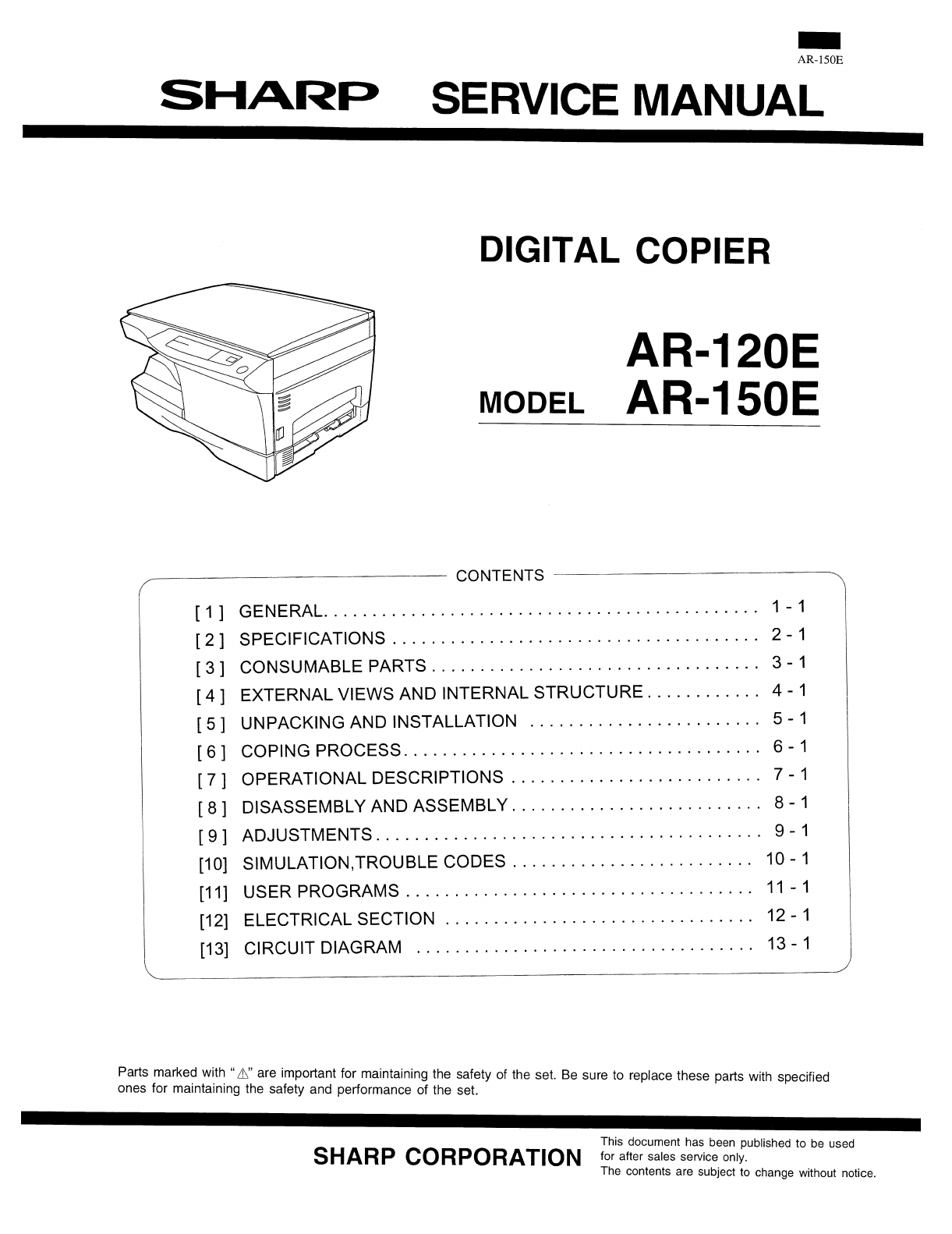
- [1] GENERAL 2
- [2] SPECIFICATIONS 3
- [The reattachment procedure] 9
- B. Drum unit 10
- [6] Printing process 22
- (–580V/–400V) 23
- Semiconductor laser 24
- [7] OPERATIONAL DESCRIPTIONS 26
- To MCU PWB 27
- 1) Basic structure 28
- 2) Laser beam path 28
- 3) Composition 28
- Heat roller 29
- Thermistor 29
- Thermal fuse 29
- Heater lamp 29
- Separator pawl 29
- [8] DISASSEMBLY AND ASSEMBLY 34
- D. Charger wire cleaning 35
- E. Charger wire replacement 35
- Note that there are 13 pawls 36
- C. Assembly procedure 37
- Heat roller disassembly 39
- B. Disassembly procedure 40
- Wire treatment 45
- Multi cover 46
- [9] Adjustment 51
- (4) Image position adjustment 57
- 1. Lead edge adjustment 57
- Document guide 58
- Copy paper 58
- (A4 or 8 1/2″ × 11″) 58
- Test chart 59
- White paper 59
- (1) Main charger (Grid bias) 60
- Procedures 60
- (2) DV bias adjustment 60
- 2. List of simulation 62
- 3. Contents of simulations 63
- 4. Trouble Codes 72
- [11] USER PROGRAM 73
- [12] ELECTRICAL SECTION 74
- A. Maiin PWB (MCU) 76
- (1) CPU signal table 76
- (2) ASIC 79
- (3) Reset circuit 86
- (5) Driver circuit (Solenoid) 88
- (7) Main motor drive circuit 88
- Mirror motor 89
- Block diagram 90
- (2) FW signal 92
- (3) Heater lamp drive circuit 92
- CL (Xenon lamp) 93
- CL- (CNT) 93
- Input +24V 93
- Selector 94
- IC902,903 94
- [13] CIRCUIT DIAGRAM 95
- AL-1000/1010 100
- POWER SUPPLY (100V/110V) 103
- POWER SUPPLY (120V/127V) 104
- POWER SUPPLY (200V Series) 105
- ACTUAL WIRING DIAGRAM 106
- SHARP CORPORATION 107
Podsumowanie treści
B. Drum unit1) Check the external view.• Check for damage or cracks on the boss and the boss hole. • Check to insure that the waste toner pipe shutter
MCU5AL-1000/101013-6
MCU6AL-1000/101013-7
OPUAL-1000/101013-8
POWER SUPPLY (100V/110V)AL-1000/101013-9
POWER SUPPLY (120V/127V)AL-1000/101013-10
POWER SUPPLY (200V Series)AL-1000/101013-11
ACTUAL WIRING DIAGRAMAL-1000/101013-12
COPYRIGHT © 1999 BY SHARP CORPORATIONAll rights reserved.Printed in Japan.No part of this publication may be reproduced,stored in a retrieval system,
7) Clean the cleaning section and the waste toner pipe to removewaste toner completely with a vacuum cleaner. 8) Remove the felt and duplex tape co
[4] EXTERNAL VIEWS AND INTERNAL STRUCTURES 1. Appearance (1) Original table (2) Original cover (3) Side cover (4) Operation panel (5) Front cover (6)
2. Operational panel (1)Exposure mode selector keyand indicators(2)Light and dark keys andexposure indicators(3) Alarm indicators∗1(4)Copy ratio selec
3. Internal(1) TC cartridge lock release button (2) TD cartridge (3) Drum cartridge(4) Drum cartridge handle (5) Paper feed roller (6) Fusing unit rel
4. Motors and solenoidsNo. Part name Control signal Function,operation(1) Main motor MM Drives the copier.(2) Mirror motor MRMT Drives the optical mir
5. Sensors and switchesNo. Name Signal Type Function Output(1)Mirror home positionsensorMHPS Transmission sensor Mirror (scanner unit)home position de
6. PWB unitNo. Name Function(1) Exposure lamp invertor PWB Exposure lamp (Xenon lamp) control(2) Main PWB (MCU) Copier control(3) Operation PWB Operat
7. Cross sectional viewNo. Part name Function and operation (1) Scanner unitIlluminates the original with the copy lamp and passes the reflected light
[5] UNPACKING AND INSTALLATION1. A WORD ON COPIER INSTALLATIONImproper installation may damage the copier. Please note thefollowing during initial ins
[1] GENERAL1. Major functionsItemCPM SB/MB 2 Tray SPF R-SPF FAXGDIwith USBGDIwithoutUSBPCLwith USBSOPM DuplexModelAR-120E 12CPM SB OptAR-150E 15CPM SB
3. UNPACKINGUnpack the copier and carry it to the installation location byholding the handles on both sides of the copier.4. REMOVING PROTECTIVE PACKI
(7) Close the front cover and then the side cover by pressingthe round projections near the side cover open button.6. LOADING COPY PAPER (installing t
[6] Printing process(1) Functional diagram(Basic operation cycle)ExposureMain high voltage unitSaw toothChargeDrumCleaningCleaning bladeWaste toner bo
(2) Outline of print processThis printer is a non-impact printer that uses a semiconductorlaser and electrostatic print process. This printer uses an
Toner is attracted over the shadowed area because of thedeveloping bias.Step-4: TransferThe visible image on the drum surface is transferred onto thep
Start1) Because the grid potential is at a low level, the drum poten-tial is at about –400V. (Carrier may not be attracted thoughthe carrier is pulled
[7] OPERATIONAL DESCRIPTIONS(1) Outline of operationThe outline of operation is described referring to the basic configuration.(Basic configuration)Ou
(2) Scanner section1) How to scan documentsThe scanner has sensors that are arranged in a line. These sensorsscan a certain area of a document at a ti
(3) Laser unitThe image data sent from the MCU (image process circuit) issent to the LSU (laser unit), where it is converted into laserbeams.1) Basic
Fuser section1. General descriptionGeneral block diagram (cross section)Top viewA. Heat rollerA pressure roller is used for the heat roller and a sili
[2] SPECIFICATIONS1. Copy modeA. TypeType Desk-topB. Machine compositionAR-120E 12 cpm / 1 tray / SBAR-150E 15 cpm / 1 tray / SB / SOPM(1) OptionMachi
Paper feed section and paper transport section1. Paper transport path and general operations(1) Scanner unit (6) Main charger (11) Pickup roller(2) Co
3. After about 0.1 sec from when the main motor start rotating,the tray paper feed solenoid (PFS) turns on at a moment.This disengages the paper feed
B. Manual multi paper feed operation1. Before paper feed operation, the manual paper feedsolenoid (MPFS) is turned OFF as shown in the figurebelow.2.
5. The solenoid turns off to close the gate and return to the in-itial state.C. Conditions of occurrence of paper misfeed(1) When the power is turned
[8] DISASSEMBLY AND ASSEMBLYBefore disassembly, be sure to disconnect the power cord forsafety.The disassembly and assembly procedures are described f
D. Charger wire cleaning(1) Remove the charger cleaner from the manual paper feedunit.(2) Set the charger cleaner to the transfer unit, and move itrec
2. Operation panel sectionA. ListNo. Part name Ref. page1 Operation panel unit 8-32 Operation PWB 8-3B. Disassembly procedure(1) Remove the screws (4
(2) Remove the screws (2pcs.), and remove the copy lampunit from the mirror base drive wire.(3) Pull the copy lamp unit toward you to remove the harne
4. Fusing sectionA. ListNo. Part name Ref. page1 Thermistor 8-52 PPD2 sensor 8-53 Heater lamp 8-64 Pressure roller 8-55 Heat roller 8-5B. Disassembly
(7) Remove the plate spring on the right and remove theheater lamp.(8) Remove the spring and remove the separation pawls (3pcs.).(9) Remove the E-ring
(6) Remove the C-ring and the fusing bearing, and remove theheat roller.(7) Remove the parts from the heat roller.Note: Apply grease to the sections s
(3) Remove two screws and remove the toner motor.(4) Remove two springs and open the intermediate frame unit.(5) Remove the pulleys on the both sides
(7) Release the belt pulley (a) lock and remove the belt pulleybearing.(8) Remove the paper exit roller.(9) Remove the harness guide.(10) Remove five
(11) Remove the parts as shown below, and remove the pres-sure release solenoid and the paper feed solenoid.(12) Remove six screws and remove the LSU
(17) Remove three screws and remove the TC front paperguide.(18) Remove the screw and the connector, and remove thePPD1 sensor PWB.(19) Remove two E-r
6. Manual paper feed sectionA. ListNo. Part name Ref. page1 Manual transport roller 8-152 Cassette detection switch 8-133 PPD1 sensor PWB 8-134 Side d
(4) Remove the PPD1 sensor PWB.(5) Remove the E-ring and remove the manual paper feedtransport roller.(6) Remove the cassette detection switch.(7) Rem
Multi unit(1) Remove the screw and remove the multi upper cover.(2) Remove the screw and remove the side door detectionunit.(3) Remove three screws an
(5) Remove three E-rings and remove the manual paper feedroller B9.(6) Remove the pick-up roller.(7) Cut the binding band and remove the multi paper f
7. Rear frame section A. ListNo. Part name Ref. page1 Mirror motor 8-162 Main motor 8-163 Exhaust fan motor 8-16B. Disassembly procedure(1) Remove thr
8. Power sectionA. ListNo. Part name Ref. page1 Power PWB 8-17B. Disassembly procedure(1) Remove two screws and one connector, and remove thepower PWB
[9] Adjustment1. Optical section(1) Image distortion adjustmentThere are following two types of image distortion.● Horizontal image distortion● Vertic
5) Loosen the copy lamp unit/No.2/3 mirror unit drive pulleysetscrew in the side where No.2/3 mirror unit does notmake contact with No.2/3 mirror unit
10) Check the horizontal image distortion.If LL = LR, there is no horizontal distortion11) If LL is not equal to LR, perform the following proce-dure.
3) If the right-left distortion balance is improper, loosen thefixing screw of No.2/3 mirror unit rail to change and ad-just the right-left balance of
2) Set the copy magnification ratio to 100%. 3) Make a copy on A4 or 81⁄2″ × 11″ paper. 4) Measure the length of the copied scale image. 5) Calculate
4) Measure the length of the copied scale image. 5) Calculate the sub scanning direction copy magnificationratio.Sub scanning direction copy magnifica
(4) Image position adjustmentThere are following five kinds of image position adjustments,which are made by laser control except for the image scan st
4) If the measurement value is out of the specified range,change the set value and repeat the adjustment procedure.The default value is 50.Note: The r
(4) Features of copy density adjustmentFor the copy density adjustment, the image data shift functionprovided in the image process LSI is used.List of
N. Additional functionsAuto paper selection (APS) NoAuto magnification ratioselection NoBinding margin No1 set 2 copy NoEdge erase NoCenter erase NoCo
3. High voltage adjustment(1) Main charger (Grid bias)Note:● Use a digital multi meter with internal resistance of10MΩ or more measurement.● After adj
[10] SIMULATION , TROUBLE CODES1.Entering the simulation modeTo enter the serviceman simulation mode, press the keys as follows:Clear Density s
2. List of simulationMain code Sub code Contents1 1 Scanner unit operation check5 1 Operation panel display lamps operation check2 Fusing lamp and coo
3. Contents of simulationsMain code Sub code Contents1 1 Scanner unit operation check(Operation/Procedure)1. When this simulation is executed, the mir
Main code Sub code Contents8 1 Developing bias check(Operation/Procedure)When the START key is pressed, the developing bias is outputted for 30 sec.2
Main code Sub code Contents24 7 Drum counter clear(Operation/Procedure)When the START key is pressed, the drum counter value is reset to 0.13 Scanner
Main code Sub code Contents26 20 Rear edge void setting(Operation/Procedure)1. When this simulation is executed, the currently set code number of rear
Main code Sub code Contents30 1 Paper sensor status display(Operation/Procedure)The paper sensor status is displayed on the copy quantity display.Sens
Main code Sub code Contents46 1 Relationship between the displayed values and the GAMMA ADJUST registerExp1 Exp2 Exp3 Exp4 Exp5AE -24 -12 0 +12 +24TEX
Main code Sub code Contents50 1 Lead edge position and paper lead edge/rear edge void adjustmentUsed to adjust the copy image position on copy paper
5) Tilt the DV box unit and rotate the DV18T clockwise to removedeveloper.6) Clean the DV box unit by sucking or blowing with a vacuum cleanerto remov
Main code Sub code Contents51 2 * Machine with the multi manual paper feed unit installedAdjustment mode Lamps ONMain cassette paper feed AE, main cas
4. Trouble CodesMain code Sub code Trouble content Detail of troubleE7 03 HSYNC cannot bedetected.LSU (laser diode, reception element, APC circuit) tr
[11] USER PROGRAMThe conditions of factory setting can be changed according to the use conditions.Functions which can be set with the user programFunc
[12] ELECTRICAL SECTION1. Block diagramA. Overall block diagramASICCPUEPROM SRAM EEPROMCCDLSUSRAMCNReferenceOPE PANELCNCRUResetSwitchPower UnitHigh Vo
B. Main PWB block diagram (Load drive block diagram)PAPERCASSETTE1TRAY EMPTYDETECTORPAPER FEEDSOLENOIDPAPERCASSETTE2TRAY EMPTYDETECTORPAPER FEEDSOLENO
2. Circuit descriptionsA. Maiin PWB (MCU)(1) CPU signal tableCPU pin tableModel without SPFPIN No Signal code Input/output Operating 1 /CS1 Output Chi
PIN No Signal code Input/output Operating 45 D4 Data input/output Data Bus46 D5 Data input/output Data Bus47 D6 Data input/output Data Bus48 D7 Data i
PIN No Signal code Input/output Operating 94 SELIN3 Output Input select 395 SELIN2 Output Input select 296 SELIN1 Output Input select 197 PR Output Po
(2) ASIC1. OutlineFig. 4 shows the block diagram of the ASIC.The ASIC is composed of the following three blocks; the image process section, the print
17) Replace the IC connector.Check that there is no oil on the IC connector pins. (Do not touchwith fingers.)Put a white mark on the above position.At
2. ASIC input/outputPIN No. Signal name IN/OUT Connected to Description1 /SCANSP IN CPU (I/O) Scanner process interrupt signal2 /PRSTART IN CPU Print
PIN No. Signal name IN/OUT Connected to Description49 MAD2 OUT DRAM Address bus of DRAM (page memory)50 MAD3 OUT DRAM Address bus of DRAM (page memory
PIN No. Signal name IN/OUT Connected to Description97 /ESPRD INElectronic sortboard(Not used)98 GND Power99 /ESREQ OUTElectronic sortboard(Not used)10
PIN No. Signal name IN/OUT Connected to Description136 GND Power137 SD17 IN/OUTSRAM(separation)Data line to SRAM before are separation138 SOE1 OUTSRAM
PIN No. Signal name IN/OUT Connected to Description165 SAD10 OUTSRAM(separation)Address line to SRAM before area separation166 SAD11 OUTSRAM(separatio
PIN No. Signal name IN/OUT Connected to Description204 PORTOUT20 OUT (Not used)205 OP-LATCH OUT Tr array IC Latch signal for operation circuit. Data l
PIN No. Signal name IN/OUT Connected to Description250 /CPUWR IN CPU CPU write signal251 /CPURD IN CPU CPU read signal252 GND Power253 CPUCLK IN CPU C
(4) Heater lamp control circuit(1) OutlineThe heater lamp control circuit detects the heat roller surfacetemperature and converts in into a voltage le
The lower the heat roller surface temperature is, the greater thethermistor resistance is, and vise versa.Therefore, the lower the heat roller surface
2TDA13TDB9RSA3REFA14REFB10RSB5IN /A8IN A16IN/B 17IN B7VSA12VSB1OUT A6OUT A11OUT B18OUT B4GA15GBIC118SLA7027MUCPUCP101ICP-N38(ROHM)24VC32147µ35VM5VC357
Remove the side sheets on the both sides of DV box unit.Clean the DV box unit with alcohol and reattach the side sheets F and R to the both sides.00.5
(9) Power circuit block diagramBlock diagramThe power circuit is composed of the main section, the high voltage circuit, the FW signal section, and th
Circuit descriptions(1) Main section a. Noise filter circuitThe noise filter circuit of the DC power is composed ofL and C as shown in the figure belo
e. Control circuitThe secondary side outputs (24V series, 5V series) aredetected by the output voltage detecting circuit, and thedetected signal is fe
(10) Cl invertor PWB (circuit) Circuit description The Two transistors connected in series to the transformer are switched on/off by the control signa
The amplified CCD signal output is sent to the clamp circuit. In the clamp circuit, the black level is clamped to 2V at the BCLK signaltiming by the a
[13] CIRCUIT DIAGRAMAC INTERLOCKAL-1000/101013-1
MCU1AL-1000/101013-2
MCU2AL-1000/101013-3
MCU3AL-1000/101013-4
MCU4AL-1000/101013-5
Powiązane produkty i podręczniki dla Kopiarki Sharp AR-150E
 (36 strony)
(170 strony)
(36 strony)
(170 strony)
 (88 strony)
(34 strony)
(181 strony)
(12 strony)
(5 strony)
(13 strony)
(58 strony)
(24 strony)
(88 strony)
(34 strony)
(181 strony)
(12 strony)
(5 strony)
(13 strony)
(58 strony)
(24 strony)
© 2020, manymanuals.pl. Wszelkie prawa zastrzeżone. | 0.028 s |
 Manymanuals.com
 Manymanuals.de
 Manymanuals.fr
 Manymanuals.it
 Manymanuals.pl
 Manymanuals.cz
 Manymanuals.es
 Manymanuals-pt.com
Komentarze do niniejszej Instrukcji