Sharp CD-C662 Dokumentacja Strona 22
- Strona / 60
- Spis treści
- BOOKMARKI
- SERVICE 1
- 1. Precautions 2
- Precautions 3
- 2. Reference Information 4
- Reference Information 5
- Samsung Electronics 2-3 6
- 2-2 IC Blocks 7
- 2-2-2 IC301 (SS11501M) 8
- 2-2-3 IC302 (LA7411) 9
- 2-2-4 IC303 (SS23378M) 10
- 2-8 Samsung Electronics 11
- 3-1 Product Specifications 12
- 3-2 Comparison Chart 13
- 4. Disassembly and Reassembly 14
- 4-1-2 Bottom cover removal 15
- Disassembly and Reassembly 16
- 4-1-4 Ass’y Function removal 17
- 4-1-5 Chassis Removal 18
- 4-2 Circuit Board Locations 19
- Samsung Electronics 4-7 20
- 4-8 Samsung Electronics 21
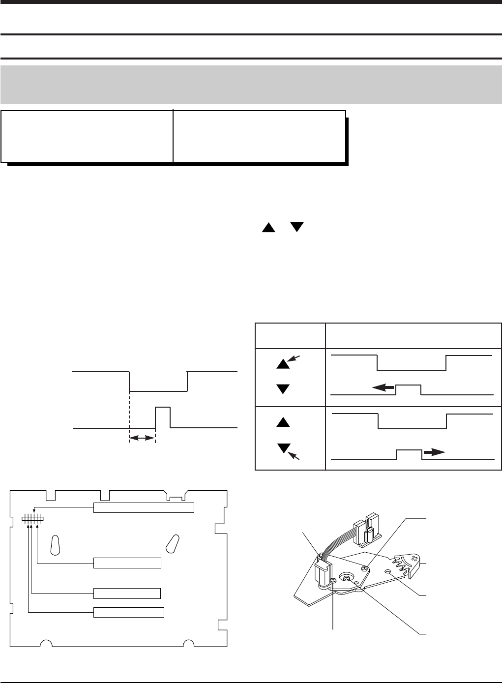
- 5. Alignment and Adjustment 22
- 5-2 Electrical Adjustment 23
- Alignment and Adjustment 24
- 5-4 Samsung Electronics 25
- Samsung Electronics 6-1 26
- 6-1 Cabinet Assembly 27
- Exploded View and Parts List 28
- 6-4 Samsung Electronics 29
- 6-6 Samsung Electronics 31
- 6-4 Housing Assembly 33
- 6-10 Samsung Electronics 35
- 7. Electrical Parts List 36
- Electrical Parts List 37
- DO NOT ORDER 46
- ASSY-FUNCTION (S.N.A) 46
- AC93-10042K 47
- ASSY-REMOCON 47
- (TSEC LOCAL) 47
- 8. Block Diagrams 48
- 8-1 Overall Block Diagram 49
- 8-2 System Control/Servo 50
- 8-3 Audio/Video 51
- ASS'Y MAIN 52
- ASS'Y FUNCTION 52
- 11. Schematic Diagrams 53
- Schematic Diagrams 54
- 11-1 S.M.P.S/POWER 55
- 11-2 System Control/Servo 56
- 11-3 Audio/Video 57
- 11-4 I/O 58
- 11-5 Function 59
- 11-6 Remote-Control 60
Powiązane produkty i podręczniki dla Odtwarzacze kasetowe Sharp CD-C662
 (56 strony)
(56 strony)
(56 strony)
 (35 strony)

 (120 strony) (32 strony)
(36 strony)
(116 strony)
(120 strony) (32 strony)
(36 strony)
(116 strony)
© 2020, manymanuals.pl. Wszelkie prawa zastrzeżone. | 0.093 s |
 Manymanuals.com
 Manymanuals.de
 Manymanuals.fr
 Manymanuals.it
 Manymanuals.pl
 Manymanuals.cz
 Manymanuals.es
 Manymanuals-pt.com
Komentarze do niniejszej Instrukcji