Sharp R-630DW Instrukcja Obsługi
Przeglądaj online lub pobierz Instrukcja Obsługi dla Kuchenki mikrofalowe Sharp R-630DW. R-630DK R-630DW R-630DS SERVICE MANUAL Instrukcja obsługi
- Strona / 44
- Spis treści
- ROZWIĄZYWANIE PROBLEMÓW
- BOOKMARKI
- SERVICE MANUAL 1
- BEFORE SERVICING 2
- WARNING TO SERVICE PERSONNEL 3
- SERVICE MANUAL 5
- SPECIFICATION 6
- GENERAL INFORMATION 6
- OVEN DIAGRAM 7
- OPERATION 8
- MICROWAVE 9
- TROUBLESHOOTING GUIDE 12
- CONDITION 13
- TEST PROCEDURES 14
- TOUCH CONTROL PANEL ASSEMBLY 22
- LSI(IXA054DR) 23
- 16.7 msec 24
- During cooking 24
- Output voltage 25
- TOUCH CONTROL PANEL SERVICING 26
- WARNING AGAINST HIGH VOLTAGE: 27
- WARNING FOR WIRING 27
- POWER TRANSFORMER REMOVAL 28
- OVEN CAVITY ASSEMBLY REMOVAL 28
- MAGNETRON REMOVAL 29
- FAN MOTOR REMOVAL 29
- TURNTABLE MOTOR REMOVAL 30
- POSITIVE LOCK 30
- DOOR REPLACEMENT 31
- INDIVIDUAL DOOR PARTS REMOVAL 32
- Printed wiring board 33
- Liquid Crystal 33
- Display (LCD) 33
- Ribbon cable 33
- Figure S-1. Pictorial Diagram 34
- Figure S-3. CPU Unit Circuit 36
- SENSOR DEFROST TURNTABLE 37
- COOK HELP 37
- PARTS LIST 39
- Not replaceable items 41
- OVEN AND CABINET PARTS 42
- DOOR PARTS 43
- MISCELLANEOUS 43
Podsumowanie treści
R-630DKR-630DWR-630DSIn the interest of user-safety the oven should be restored to its originalcondition and only parts identical to those specified s
8R-630DKR-630DWR-630DSFigure O-1. Oven Schematic-Off ConditionSCHEMATICNOTE: CONDITION OF OVEN1. DOOR CLOSED2. CLOCK APPEARS ON DISPLAYSCHEMATICNOTE:
9R-630DKR-630DWR-630DSDESCRIPTION AND FUNCTION OF COMPONENTSDOOR OPEN MECHANISMThe door is opened by pulling the door. Refer to the FigureD-1.Figure D
10R-630DKR-630DWR-630DSTROUBLESHOOTING GUIDENever touch any part in the circuit with your hand or an uninsulated tool while the power supply is connec
11R-630DKR-630DWR-630DSHome fuse or circuit breaker blowswhen power cord is plugged into wallreceptacleMonitor fuse blows when power cordis plugged in
12R-630DKR-630DWR-630DSB POWER TRANSFORMER TESTA MAGNETRON ASSEMBLY TEST1. Disconnect the power supply cord, and then remove outer case.2. Open the do
13R-630DKR-630DWR-630DS(HIGH VOLTAGES ARE PRESENT AT THE HIGH VOLTAGE TERMINAL, SO DO NOT ATTEMPT TOMEASURE THE FILAMENT AND HIGH VOLTAGE.)TEST PROCED
14R-630DKR-630DWR-630DSTEST PROCEDURESPROCEDURELETTERCOMPONENT TEST1. Disconnect the power supply cord, and then remove outer case.2. Open the door an
15R-630DKR-630DWR-630DSTEST PROCEDURESPROCEDURELETTERCOMPONENT TEST1. Disconnect the power supply cord, and then remove outer case.2. Open the door an
16R-630DKR-630DWR-630DSK RELAY TESTTEST PROCEDURESPROCEDURELETTERCOMPONENT TESTJ KEY UNIT TEST2-1 In connection with pads.a) When touching the pads, a
17R-630DKR-630DWR-630DSTEST PROCEDURESPROCEDURELETTERCOMPONENT TEST6. After that procedure, re-connect the power supply cord.7. Remove the outer case
R-630DKR-630DWR-630DSPRECAUTIONS TO BE OBSERVED BEFORE ANDDURING SERVICING TO AVOID POSSIBLEEXPOSURE TO EXCESSIVE MICROWAVEENERGY(a) Do not operate or
18R-630DKR-630DWR-630DSTEST PROCEDURESPROCEDURELETTERCOMPONENT TEST6) Reconnect all leads removed from componentsduring testing.7) Re-install the oute
19R-630DKR-630DWR-630DSTEST PROCEDURESPROCEDURELETTERCOMPONENT TESTWARNING : The oven should be fully assembled before following procedure.Make sure t
20R-630DKR-630DWR-630DSTOUCH CONTROL PANEL ASSEMBLYOUTLINE OF TOUCH CONTROL PANELThe touch control section consists of the following units.(1) Key Uni
21R-630DKR-630DWR-630DS1 AN10 IN Signal coming from touch key.When either G10 line on key matrix is touched, a corresponding signal out of P10 - P17wi
22R-630DKR-630DWR-630DS23 P24 OUT Oven lamp, fan motor and turntable motor driving signalTo turn on and off shut off relay (RY1). Thesquare waveform v
23R-630DKR-630DWR-630DS95-98 AN4-AN7 IN Terminal to change cooking input according to the Model.By using the A/D converter contained in the LSI, DC vo
24R-630DKR-630DWR-630DS1. Precautions for Handling Electronic ComponentsThis unit uses CMOS LSI in the integral part of thecircuits. When handling the
25R-630DKR-630DWR-630DSTo remove the outer case, proceed as follows.1. Disconnect the power supply cord.2. Open the oven door and block it open.3. To
26R-630DKR-630DWR-630DSPOWER TRANSFORMER REMOVALReinstallation1. Rest transformer on the base plate with its primaryterminals toward the left side.2.S
27R-630DKR-630DWR-630DSOven lampsocketTerminalWire leadTerminal holeFlat type smallscrew driverMAGNETRON REMOVALRemoval1. Disconnect the power supply
1R-630DKR-630DWR-630DSWARNING TO SERVICE PERSONNELMicrowave ovens contain circuitry capable of pro-ducing very high voltage and current, contact withf
28R-630DKR-630DWR-630DS12.Remove the fan motor with the fan motor mounting anglefrom the fan case assembly and the cross flow fan.13.Remove the two (2
29R-630DKR-630DWR-630DS1. Disconnect the power supply cord, and then removeouter case.2. Open the door and block it open.3. To discharge the high volt
30R-630DKR-630DWR-630DSSealer filmBacking filmAdhesive tapeNote:The door on a microwave oven is designed to act asan electronic seal preventing the le
31R-630DKR-630DWR-630DSFigure C-10. Routing of wire harnessNOTE: For key sheet1. Before attaching a new key sheet, wipe offremaining adhesive on the d
32R-630DKR-630DWR-630DS645123645123ABCDEFGHABCDEFGHFigure S-1. Pictorial DiagramHIGH VOLTAGECAPACITORHIGH VOLTAGEWIRE BH.V.RECTIFIERPOWER SUPPLY CORD
33R-630DKR-630DWR-630DS645123645123ABCDEFGHABCDEFGHFigure S-2. Power Unit CircuitA 1ACCN-ACN-BCN-CCN-FACC10C 7C 6C 1C 5C 4C 8C 9C 3C 2C12C11A 2NOCOMNO
34R-630DKR-630DWR-630DS645123645123ABCDEFGHABCDEFGHFigure S-3. CPU Unit CircuitC10C 5C 7C 1C 8C 4C 9C 6C 2C11C12G 9G 8 G 7 G 6 G 5 G 4 G 3 G 2 G 1G12
35R-630DKR-630DWR-630DSFigure S-4. Indicator Circuit645123645123ABCDEFGHABCDEFGHVCGNDIC1 P91OSC4VC1VC2VC3VC4VC5CFCECDCCCBCACOM8COM9COM10COM11COM12COM1
36R-630DKR-630DWR-630DS645123645123ABCDEFGHABCDEFGHFigure S-5. Printed Wiring Board of Power Unit31481122111(D9)C50C3C51D1C2ECBQ1JXJYR53CN - BCN - FCN
37R-630DKR-630DWR-630DS***∆*∆PARTS LISTNote: The parts marked “∆” may cause undue microwave exposure.The parts marked “*” are used in voltage more tha
2R-630DKR-630DWR-630DSMICROWAVE MEASUREMENT PROCEDUREA. Requirements:1) Microwave leakage limit (Power density limit): The power density of microwave
38R-630DKR-630DWR-630DS∆∆∆∆∆∆∆*REF. NO. PART NO. DESCRIPTION Q'TY CODE4-10 PPACGA084WRF0 TTM packing 1 AE4-11 LANG-A081WRWZ Separate angle B 1 AD
39R-630DKR-630DWR-630DSPACKING AND ACCESSORIESHOW TO ORDER REPLACEMENT PARTSTo have your order filled promptly and correctly, please furnish the follo
40R-630DKR-630DWR-630DS645123645123ABCDEFGHABCDEFGH7-37-117-111-27-22-44-264-174-234-244-304-287-51-157-187-146-91-136-84-121-17-37-117-116-74-274-184
41R-630DKR-630DWR-630DS645123645123ABCDEFGHABCDEFGHDOOR PARTSMISCELLANEOUSActual wire harness may be different from illustration.(CAPACITOR)5-135-135
42R-630DKR-630DWR-630DS2000 SHARP CORP. (7S2.530E) Printed in U.S.ACOPYRIGHT © 2000 BY SHARP CORPORATIONALL RIGHTS RESERVED.No part of this publicatio
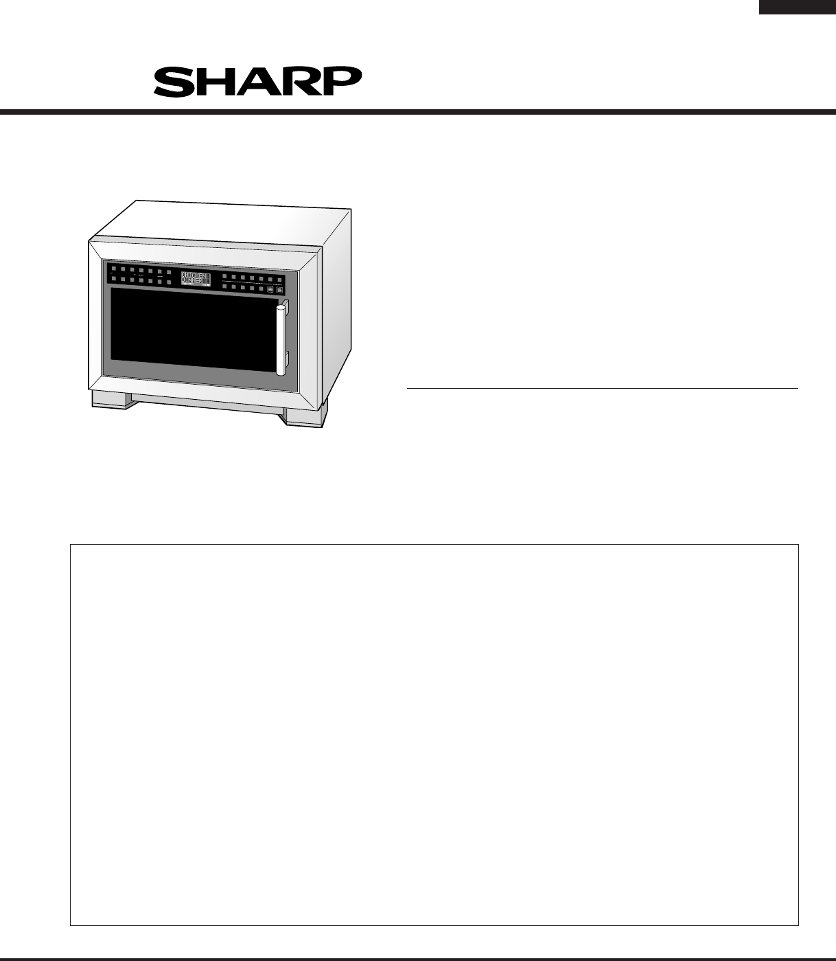
3R-630DKR-630DWR-630DSSHARP ELECTRONICS CORPORATIONSHARP PLAZA, MAHWAH,NEW JERSEY 07430-2135SERVICE MANUALMICROWAVE OVENR-630DK/ R-630DW/ R-630DSFOREW
4R-630DKR-630DWR-630DSITEM DESCRIPTIONPower Requirements 120 Volts / 14 Amperes60 HertzSingle phase, 3 wire groundedPower Output 1100 watts (IEC TEST
5R-630DKR-630DWR-630DSWhere a two-pronged wall-receptacle is encountered, it is the personalresponsibility and obligation of the customer to contact a
6R-630DKR-630DWR-630DSOPERATIONDESCRIPTION OF OPERATING SEQUENCEThe following is a description of component functions duringoven operation.OFF CONDITI
7R-630DKR-630DWR-630DSAn example of how sensor works: (POTATOES)1. Potates at room temperature. Vapor is emitted veryslowly.2. Heat Potates. Moisture
Powiązane produkty i podręczniki dla Kuchenki mikrofalowe Sharp R-630DW
 (392 strony)
(40 strony)
(26 strony)
(392 strony)
(40 strony)
(26 strony)
© 2020, manymanuals.pl. Wszelkie prawa zastrzeżone. | 0.072 s |
 Manymanuals.com
 Manymanuals.de
 Manymanuals.fr
 Manymanuals.it
 Manymanuals.pl
 Manymanuals.cz
 Manymanuals.es
 Manymanuals-pt.com
Komentarze do niniejszej Instrukcji