Sharp R-426H Instrukcja Obsługi
Przeglądaj online lub pobierz Instrukcja Obsługi dla Kuchenki mikrofalowe Sharp R-426H. Sharp R-426H Technical data Instrukcja obsługi
- Strona / 194
- Spis treści
- BOOKMARKI
- TECHNICAL DATA 1
- SERVICE MANUAL 1
- Important 2
- WHO SHOULD USE THIS MANUAL 3
- TABLE OF CONTENTS 3
- Read Me First! 5
- 1-1 Unit Specifications 10
- 1-1Unit Specifications 30
- (B) Outdoor Unit 40
- Ceiling Mounted Type 47
- Concealed Duct Type 48
- Outdoor Unit 49
- 1-4 Dimensional Data 53
- 1-5 Refrigerant Flow Diagram 61
- 1-6 Operating Range 64
- 1-7 Cooling Capacity 65
- ● Heating Capacity 77
- 1-8 Noise Criterion Curves 78
- External Static Pressure 82
- Limit line 82
- 1-10 Air throw Distance Chart 83
- Tubing Length 85
- 0426_C_I 88
- 3 - ø40 hole 89
- 6 - ø6 hole 89
- 3 - ø60 hole 89
- 8 - ø6 hole 89
- Electrical Wiring 90
- 0511_M_I 91
- ■ Electrical Characteristics 93
- 1. Specifications 100
- Electrical Characteristics 100
- SM830080 105
- 2-1 Room Temperature Control 106
- SET SPEED 107
- 0673_X_S 108
- Chart Explanations and notes 109
- 2-4 Outdoor Fan Speed Control 110
- 2. Processes and functions 112
- 1566_M_S 114
- Fig. 14 116
- Fig. 13 116
- 0443_M_S 117
- (B) AUTO Control Mode 118
- (A) Cooling 119
- 0447_M_S 120
- 2-16 Dehumidifying Operation 121
- Auto-flap Control 122
- Ceiling-Mounted Type) 122
- 0451_M_S 123
- • Electric Wiring Diagram 126
- • Schematic Diagram 127
- This section explains: 139
- 0500_M_I 140
- 0499_M_I 141
- 0458_M_I 142
- 4. Service procedures 143
- (B) Heating 143
- 0654_C_I 146
- 1903_M_I 150
- 0340_M_I 151
- 0460_M_I 156
- 0652_M_S 157
- 0354_M_I 159
- Alarm message 160
- TEST RUN / CHECK button 160
- ON / OFF operation 160
- 0356_M_I 161
- Set CODE No. A1 with 165
- 0362_M_I 166
- (SET TEMP) button 168
- 0368_M_I 169
- 0639_X_S 173
- 0640_X_S 174
- 0641_X_S 174
- Multimeter 175
- 0643_X_S 176
- Indoor P.C.B. Ass’y 178
- Outdoor P.C.B. Ass’y 178
- 1251_X_I 179
- 1250_X_I 179
- • ACR 436 H - ACR 448 H 180
- Indoor Unit 180
- • ACR 425 H 180
- • ADR 425 H 181
- • ADR 436 H 181
- • ADR 448 H 181
- • AER 436 SHL3E 182
- Outdoor Units 182
- • AER 448 SHL3E 183
- Temperature (°C) 184
- 1577_C_I 188
- 1579_M_I 189
- 5. Appendix 190
- 5-1 P.C.B 191
Podsumowanie treści
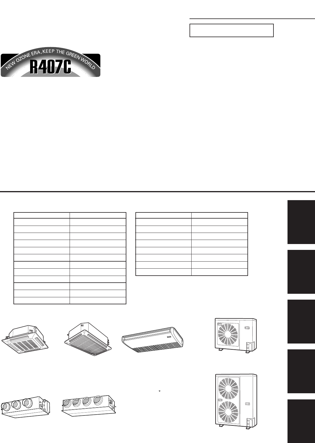
FILE NO.1Section2345TECHNICAL DATA&SERVICE MANUALASR 425 H / AER 425 SCLEASR 425 H / AER 425 SCL3EASR 436 H / AER 436 SCL3EASR 448 H / AER 448 SCL
1. Specifications12345I-51-1 Unit Specifications4-Way Air Discharge Semi-concealed TypeMODEL No. Indoor Unit ASR 448 HOutdoor Unit AER 448 SCL3EPOW
1. Specifications112345I - 1141-11 Installation InstructionsElectrical CharacteristicsIndoor Unit : ACR 448 H Outdoor Unit : AER 448 SCL3E AE
1. Specifications12345I - 1151-11 Installation InstructionsElectrical CharacteristicsIndoor Unit : ADR 425 H Outdoor Unit : AER
1. Specifications112345I - 1161-11 Installation InstructionsElectrical CharacteristicsIndoor Unit : ADR 425 H Outdoor Unit : AE
1. Specifications12345I - 1171-11 Installation InstructionsElectrical CharacteristicsIndoor Unit : ADR 436 H Outdoor Unit : AER
1. Specifications112345I - 1181-11 Installation InstructionsElectrical CharacteristicsIndoor Unit : ADR 448 H Outdoor Unit : A
2. Processes and functions12345II - 1SM8300802. PROCESSES AND FUNCTIONS2-1 Room Temperature Control ...
2. Processes and functions112345II - 22-1 Room Temperature ControlThe unit adjusts room temperature by turning the outdoor unit’s compressor ON and OF
2. Processes and functions12345II - 3(B) HeatingChart Summary and Explanations❑ Once the compressor starts, it keeps running for 5 minutes.❑ Once the
2. Processes and functions112345II - 42-2 Cold Draft Prevention (Heating Cycle)The cold draft prevention function controls indoor fan speed so a stron
2. Processes and functions12345II - 5Chart Explanations and notes❑ When the fan speed changes, it keeps the speed step for at least 1 minute, even if
1. Specifications112345I-61-1 Unit Specifications4-Way Air Discharge Semi-concealed TypeMODEL No. Indoor Unit ASR 425 HOutdoor Unit AER 425 SHLEPOWER
2. Processes and functions112345II - 62-4 Outdoor Fan Speed ControlTo optimize performance in air conditioner, the outdoor fan speed is selected autom
2. Processes and functions12345II - 72-5 Freeze Prevention (Cooling)Freeze Prevention keeps the indoor heat exchange coil from freezing. Freezing redu
2. Processes and functions112345II - 82-6 Condensing Temperature Control (Cooling)Condensing temperature is controlled by the outdoor heat exchanger c
2. Processes and functions12345II - 9Chart Explanations and notes❑ This chart shows how the outdoor fan speed and the electronic refrigerant control v
2. Processes and functions112345II - 10Chart Summary and Explanations❑ Discharge temperature is sensed by TH8 (discharge gas sensor).❑ When the tempe
2. Processes and functions12345II - 11Fig. 12Chart summary and Explanations❑ This chart shows how the Operation Mode (COOLING or HEATING) is determine
2. Processes and functions112345II - 12❑ During the defrost cycle, STANDBY appears on the remote controller.❑ *...Cold Draft Prevention may operate
2. Processes and functions12345II - 132-11 4-Way Valve, Solenoid ControlThe basic function of the 4-way valve is to direct the refrigerant in the corr
2. Processes and functions112345II - 14(B) AUTO Control ModeWhen the Compressor has stopped while in AUTO mode, the 4-way valve switches on(heating)
2. Processes and functions12345II - 152-13 Electronic Expansion Valve❑ This valve allows very precise and smooth control of the amount of refrigerant
1. Specifications12345I-71-1 Unit Specifications4-Way Air Discharge Semi-concealed TypeMODEL No. Indoor Unit ASR 425 HOutdoor Unit AER 425 SHL3EPOWER
2. Processes and functions112345II - 162-15 Compressor Current Detection Circuit❑ The Compressor Current Detection Circuit detects the compressor curr
2. Processes and functions12345II - 172-16 Dehumidifying OperationDehumidifying operation uses the cooling cycle to remove moisture from the air, but
2. Processes and functions112345II - 18(1) When the unit is stopped, the Auto-flap returns to F5 position.(2) When the airflow direction is set (an op
2. Processes and functions12345II - 192-18 Controlled by Electronic Expansion ValveThe circulation volume of the refrigerant is controlled by a pulse
2. Processes and functions112345II - 202-19 Voltage Detection ControlWhen the power voltage falls below 160 V (voltage between N phase and each phase)
3. Electrical data12345III - 133. ELECTRICAL DATA3-1 Indoor Units (Electric Wiring Diagram, Schematic Diagram) ... III - 24-Way Air Di
3. Electrical data112345III - 23-1 Indoor Units111114-Way Air Discharge Semi-concealed Type : ASR 425 H - ASR 436 HASR 448 HTH1TH2TH331212121TH43121D
3. Electrical data12345III - 3• Schematic DiagramS 854-2-5268-470-00-3 (X)FMI21312121215687313121234512341TR1T20AC230V8P-U28P-U1To Outdoor UnitIndoor
3. Electrical data112345III - 43-1 Indoor Units22222Ceiling Mounted Type : ACR 425 H - ACR 436 H - ACR 448 HLMConnector9P(WHT)213131433175123456781PSP
3. Electrical data12345III - 5• Schematic Diagram S 854-2-5268-665-00-0 (TR)FMI213121212131342131321234512341TR1AC230V8P-U28P-U1Indoor CoilIndoor Coil
1. Specifications112345I-81-1 Unit Specifications4-Way Air Discharge Semi-concealed TypeMODEL No. Indoor Unit ASR 436 HOutdoor Unit AER 436 SHL3EPOWE
3. Electrical data112345III - 123-1 Indoor Units66666Concealed Duct Type : ADR 425 H - ADR 436 H - ADR 448 HTH1 TH2 TH331TH42121213121Connector9P(WHT)
3. Electrical data12345III - 133-1 Indoor Units66666Concealed Duct Type : ADR 425 H - ADR 436 H - ADR 448 H• Schematic DiagramS 854-2-5268-843-00-0 (U
3. Electrical data112345III - 143-2 Outdoor Units11111 AER 425 SCLE - AER 425 SHLE1• Electric Wiring Diagram2 3 4 NLTH6TH7TH82121213163PH3131357913113
3. Electrical data12345III - 153-2 Outdoor Units11111 AER 425 SCLE - AER 425 SHLE• Schematic DiagramFMO21311221212131TRAC 230VAC 14VTH8TH7TH62P-22P-13
3. Electrical data112345III - 163-2 Outdoor Units22222 AER 425 SCL3E - AER 425 SHL3E1• Electric Wiring Diagram2 3 4 5 67 8TH6TH7TH82121213163PH3131 35
3. Electrical data12345III - 173-2 Outdoor Units22222 AER 425 SCL3E - AER 425 SHL3E• Schematic DiagramFMO21311221212131TRAC 230VAC 14VTH8TH7TH62P-22P-
3. Electrical data112345III - 183-2 Outdoor Units33333 AER 436 SCL3E - AER 436 SHL3E - AER 448 SCL3E - AER 448 SHL3E1• Electric Wiring Diagram2 3 45 6
3. Electrical data12345III - 193-2 Outdoor Units33333 AER 436 SCL3E - AER 436 SHL3E - AER 448 SCL3E - AER 448 SHL3E• Schematic DiagramFMO2213112212121
4. Service procedures12345IV-14. SERVICE PROCEDURES4-1 Troubleshooting ...
4. Service procedures112345IV - 24-1 TroubleshootingThis section explains:This unit is made to be trouble free, and not need much service. However, w
1. Specifications12345I-91-1 Unit Specifications4-Way Air Discharge Semi-concealed TypeMODEL No. Indoor Unit ASR 448 HOutdoor Unit AER 448 SHL3EPOWER
4. Service procedures12345IV-3(1)-1 Check before and after Troubleshooting (AER 425 SHLE)Many problems may happen because of wiring or power supply pr
4. Service procedures112345IV - 4 Power Supply: 50 Hz, 3-phase, 380-400-415 V12U1U2R1R2R3123123124L1L2L3NIndoor UnitInter-unitpower wiring(Line v
4. Service procedures12345IV-5(2) General Troubleshooting Flow Chart: Diagnosis and RemedyWhen you have found a major problem, such as refrigerant not
4. Service procedures112345IV - 6(B) HeatingPoor heatingIs setting temp.suitable ?Change the setting temp.Is heating loadtoo large ?Review heating loa
4. Service procedures12345IV-7(3) Meanings of alarm messagesIf an error occurred in the air conditioner, the error condition is presented by indicatin
4. Service procedures112345IV - 8Wired remotecontrollerdisplayWireless remotecontrollerdisplayPossible causes of troubles• Thermistor failureOperation
4. Service procedures12345IV-9(4) LED Indication on the Outdoor Unit’s P.C.B. Ass’yIf something goes wrong with the outdoor unit, LED lamps on the ou
4. Service procedures112345IV - 10(5) Symptoms and parts to inspect1) Symptom: LCD on the remote controller does not display and remote controller doe
4. Service procedures12345IV - 112) Symptom: LCD on the remote controller displays “CHECK E01”.(Unusual communication between remote controller and in
4. Service procedures112345IV - 124) Symptom: LCD on the remote controller is displaying “CHECK E04”. (Unusualcommunication between the indoor and ou
1. Specifications112345I-101-1 Unit SpecificationsCeiling Mounted TypeMODEL No. Indoor Unit ACR 425 HOutdoor Unit AER 425 SCLEPOWER SOURCE 220 - 230 -
4. Service procedures12345IV - 136) Symptom: LCD on the remote controller is displaying “CHECK E06”. (Unusualcommunication between the indoor and out
4. Service procedures112345IV - 149) Symptom: LCD on the remote controller displays “CHECK P01”. (Indoor fanprotection thermostat operation warning)N
4. Service procedures12345IV - 1510) Symptom: LCD on the remote controller displays “CHECK P02”. (Compressor /outdoor fan protection thermostat opera
4. Service procedures112345IV - 1611) Symptoms: LCD on the remote controller displays “CHECK P03”.(Alarm for unusual discharge temp. of compressor)12)
4. Service procedures12345IV - 1713) Symptom: LCD on the remote controller displays “CHECK P05”. (Negative phasedetection operation warning)YesNoNoNo
4. Service procedures112345IV - 1815) Symptom: LCD on the remote controller displays “CHECK E16”.NoNoNoYesYes0647_M_SStartRepair the wiring.When the g
4. Service procedures12345IV - 1917) Symptom: LCD on the remote controller displays “CHECK H01, H02, H03”. (PCcompressor current detection)* Please c
4. Service procedures112345IV - 20(6) Procedures When a Specific Component Does Not Work1) Indoor fan does not operate.3) Flap does not operate, when
4. Service procedures12345IV - 214) Compressor motor does not operate.5) Outdoor fan does not operate.NoYesNoYesIs fan motor capacitor normal ?NoIs th
4. Service procedures112345IV - 22(7) Service Functions of Remote ControllerFrom the remote controller you can control both the operation and settings
1. Specifications12345I-111-1 Unit SpecificationsCeiling Mounted TypeMODEL No. Indoor Unit ACR 425 HOutdoor Unit AER 425 SCL3EPOWER SOURCE 380 - 400 -
4. Service procedures12345IV - 23(B) Use the test run procedure❏ The purpose of the test run function is to let you control the operation of the unitd
4. Service procedures112345IV - 24(C) Check the sensor temperature readingsThe air conditioner has thermo sensors which are used to control the unit.❏
4. Service procedures12345IV - 25Refer to the table below for the relationship between the sensor address and the locationof the sensor.In case there
4. Service procedures112345IV - 26This picture shows the service check display.For example, if the last four alarm messages were, in order of occurren
4. Service procedures12345IV - 27Never press CL (clear) button unless you want to erase the accessed data in memory.Follow the procedure below only wh
4. Service procedures112345IV - 28(F) Execute the auto. address operation❏ Auto. address operation is executed by pressing the A. ADD (S1) button of o
4. Service procedures12345IV - 29(G) Confirm and change the indoor unit address❏ The purpose of the above function is to let you confirm the indoor un
4. Service procedures112345IV - 30e Set the required new indoor unit’s No. by pressing the , ( ) button.f Press the SET button.UNIT No, SET DATA (0
4. Service procedures12345IV - 31(H) Change the shift temperature in heating mode❏ If the indoor unit is installed at high location (ex. ceiling level
4. Service procedures112345IV - 32( I ) Set the indoor unit address❏ This function is usable if the auto. address operation is not available.Indoor un
1. Specifications112345I-121-1 Unit SpecificationsCeiling Mounted TypeMODEL No. Indoor Unit ACR 436 HOutdoor Unit AER 436 SCL3EPOWER SOURCE 380 - 400
4. Service procedures12345IV - 33d Set the No. of R. C. which you want to set with , ( ) button.e Press the SET button.UNIT No., CODE No. 12,SETTIN
4. Service procedures112345IV - 34i Select the code No. 14 to set group setting with the , (SET TEMP) button.jSet the No. of group setting as shown
4. Service procedures12345IV - 35(J) Change the period of the filter timer❏ If the period of filter timer is not suitable (for example in case of dirt
4. Service procedures112345IV - 364-2 Checking the Electrical Components(1) Measurement of InsulationResistance• The insulation is in good condition i
4. Service procedures12345IV - 37(2) Measurement of InsulationResistance for Electrical parts• Disconnect the connector of the desiredelectric part fr
4. Service procedures112345IV - 38(3) Checking the Protective Devices• Disconnect the connector, which consists of P (plug) and S (socket) whenyou wan
4. Service procedures12345IV - 39(4) Checking the Electrical Parts1 Power transformer (TR1) ... Indoor unit *Measure the coil resistance
4. Service procedures112345IV - 406 Solenoid coil of the electronic refrigerant *Measure the coil resistance.control valve (ERCV) ………… Indoor unit•Mea
4. Service procedures12345IV - 410 Fuse on indoor and outdoor P.C.B. Ass’y …. Both in indoor and outdoor unit*Check the continuity.• Remove the P.C.B.
4. Service procedures112345IV - 42(5) Sensor and Solenoid Layout DiagramIndoor Unit• ASR 425 HTH3 (E2), (BLK)TH2 (E1), (RED)Electronic expansion valve
1. Specifications12345I-131-1 Unit SpecificationsCeiling Mounted TypeMODEL No. Indoor Unit ACR 448 HOutdoor Unit AER 448 SCL3EPOWER SOURCE 380 - 400 -
4. Service procedures12345IV - 43• ACR 436 H - ACR 448 HTH3 (E2), (BLK)TH4 (E3), (BRN)1219_THS_ITH2 (E1), (RED)Electronic expansion valveTH4 (E3), (BR
4. Service procedures112345IV - 44SM830080Heat exchTH5 (Discharge Air)1264_C_ITH3 (E2), (BLK)TH2 (E1), (RED)Electronic expansion valveTH4 (E3), (BRN)1
4. Service procedures12345IV - 45• AER 436 SHL3E0585_C_STH6 (C1), (BLK)TH7 (C2), (RED)TH6, 7, 8CMCHTH8 (GRN)( Discharge gas)63PH20S0584_C_S0583_C_STH6
4. Service procedures112345IV - 460585_C_STH6 (C1), (BLK)TH7 (C2), (RED)TH6, 7, 8CMCHTH8 (GRN)( Discharge gas)63PH20S0586_C_SOutdoor Units• AER 448 SH
4. Service procedures12345IV - 47(1) Room temp. sensor : TH1 (KTEC-35)TH5 (KTEC-35)(2) Indoor heat exch.coil sensor : TH2(E1), TH3(E2),TH4(E3)Outdoor
4. Service procedures112345IV - 48(7) P.C.B. Setting● Setting of outdoor control PCB(A) Standard control (single outdoor unit)In case of single outdoo
4. Service procedures12345IV - 49(8) R.C. Address Setting MethodOutdoor unit R.C. address setting methodIn case of group control or central control, s
4. Service procedures112345IV - 50(9) Automatic Address Setting Method— For group control and central control withmultiple outdoor units —Carry out au
4. Service procedures12345IV - 51(11) Items to Check Prior to Test Run(1) Turn on the power supply switch more than 5 hours before in order to charge
4. Service procedures112345IV - 52(12) Test Run Procedure1) One of CN4 of all linked outdoor units shold be short.2) In case of using system controlle
1. Specifications112345I-141-1 Unit SpecificationsCeiling Mounted TypeMODEL No. Indoor Unit ACR 425 HOutdoor Unit AER 425 SHLEPOWER SOURCE 220 - 230 -
5. Appendix12345V-155. APPENDIX5-1 P.C.B. ... V - 2
5. Appendix112345V-25-1 P.C.B.Outdoor Unit Control P.C.B. :AER 425 SCL3E - AER 436 SCL3E - AER 448 SCL3EAER 425 SHL3E - AER 436 SHL3E - AER 448 SHL3EC
5. Appendix12345V-35-1 P.C.B.Outdoor Unit Control P.C.B. : AER 425 SCLE - AER 425 SHLECR-CR253GHL5JP11JP8JP7JP2JP11578_C_SCN1 : VCCCN26 (WHT)CN27S2 (B
5. Appendix112345V-4When replacing the indoor unit P.C.B. for service, remove the *E2P-ROM of the original P.C.B. then attach itto the new P.C.B. sinc
• The specifications, designs, and information in this brochure are subject to change without notice.
Please Read Before StartingThis air conditioning system meets strict safety andoperating standards. As the installer or service person, itis an import
1. Specifications12345I-151-1 Unit SpecificationsCeiling Mounted TypeDATA SUBJECT TO CHANGE WITHOUT NOTICE.Cooling:Rating conditions (*): Indoor air t
1. Specifications112345I-161-1 Unit SpecificationsCeiling Mounted TypeDATA SUBJECT TO CHANGE WITHOUT NOTICE.Cooling:Rating conditions (*): Indoor air
1. Specifications12345I-171-1 Unit SpecificationsCeiling Mounted TypeDATA SUBJECT TO CHANGE WITHOUT NOTICE.Cooling:Rating conditions (*): Indoor air t
1. Specifications112345I-261-1 Unit SpecificationsConcealed Duct TypeMODEL No. Indoor Unit ADR 425 HOutdoor Unit AER 425 SCLEPOWER SOURCE 220 - 230 -
1. Specifications12345I-271-1 Unit SpecificationsConcealed Duct TypeMODEL No. Indoor Unit ADR 425 HOutdoor Unit AER 425 SCL3EPOWER SOURCE 380 - 400 -
1. Specifications112345I-281-1 Unit SpecificationsConcealed Duct TypeDATA SUBJECT TO CHANGE WITHOUT NOTICE.Cooling:Rating conditions (*): Indoor air t
1. Specifications12345I-291-1 Unit SpecificationsConcealed Duct TypeDATA SUBJECT TO CHANGE WITHOUT NOTICE.Cooling:Rating conditions (*): Indoor air te
1. Specifications112345I-301-1 Unit SpecificationsConcealed Duct TypeMODEL No. Indoor Unit ADR 425 HOutdoor Unit AER 425 SHLEPOWER SOURCE 220 - 230 -
1. Specifications12345I-311-1 Unit SpecificationsConcealed Duct TypeMODEL No. Indoor Unit ADR 425 HOutdoor Unit AER 425 HL3EPOWER SOURCE 380 - 400 - 4
1. Specifications112345I-321-1 Unit SpecificationsConcealed Duct TypeMODEL No. Indoor Unit ADR 436 HOutdoor Unit AER 436 SHL3EPOWER SOURCE 380 - 400 -
iiWHO SHOULD USE THIS MANUALThis service manual is made to assist the service technician apply his knowledge andtraining to this model air conditioner
1. Specifications12345I-33SM80081-1Unit SpecificationsConcealed Duct TypeMODEL No. Indoor Unit ADR 448 HOutdoor Unit AER 448 SHL3EPOWER SOURCE 380 - 4
1. Specifications112345I-341-2 Major Component Specifications(A) Indoor Units : 4-Way Air Discharge Semi-concealed TypeMODEL No. ASR 425 HSource 220 -
1. Specifications12345I-351-2 Major Component Specifications(A) Indoor Units : 4-Way Air Discharge Semi-concealed TypeMODEL No. ASR 436 HSource 220 -
1. Specifications112345I-361-2 Major Component Specifications(A) Indoor Units : 4-Way Air Discharge Semi-concealed TypeMODEL No. ASR 448 HSource 220 -
1. Specifications12345I-371-2 Major Component Specifications(A) Indoor Units : Ceiling Mounted TypeMODEL No. ACR 425 HSource 220 - 230 - 240 V / 1 pha
1. Specifications112345I-381-2 Major Component Specifications(A) Indoor Units : Ceiling Mounted TypeMODEL No. ACR 436 HSource 220 - 230 - 240 V / 1 ph
1. Specifications12345I-391-2 Major Component Specifications(A) Indoor Units : Ceiling Mounted TypeMODEL No. ACR 448 HSource 220 - 230 - 240 V / 1 pha
1. Specifications12345I-431-2 Major Component Specifications(A) Indoor Units : Concealed Duct TypeMODEL No. ADR 425 HSource 220 - 230 - 240 V / 1 pha
1. Specifications112345I-441-2 Major Component Specifications(A) Indoor Units : Concealed Duct TypeMODEL No. ADR 436 HSource 220 - 230 - 240 V / 1 pha
1. Specifications12345I-451-2 Major Component Specifications(A) Indoor Units : Concealed Duct TypeMODEL No. ADR 448 HSource 220 - 230 - 240 V / 1 phas
iii2-7 Overload Protection (Heating) ...II - 92-8 Discharge Temperature Control (Cool
1. Specifications112345I-461-2 Major Component Specifications(B) Outdoor UnitMODEL No. AER 425 SCLESource 220 - 230 - 240 V / 1 phase / 50 HzControlle
1. Specifications12345I-471-2 Major Component Specifications(B) Outdoor UnitMODEL No. AER 425 SHLESource 220 - 230 - 240 V / 1 phase / 50 HzController
1. Specifications112345I-481-2 Major Component Specifications(B) Outdoor UnitMODEL No. AER 425 SCL3ESource 380 - 400 - 415 V / 3 phase / 50 HzControll
1. Specifications12345I-491-2 Major Component Specifications(B) Outdoor UnitMODEL No. AER 425 SHL3ESource 380 - 400 - 415 V / 3 phase / 50 HzControlle
1. Specifications112345I-501-2 Major Component Specifications(B) Outdoor UnitMODEL No. AER 436 SCL3E AER 448 SCL3ESource 380 - 400 -
1. Specifications12345I-511-2 Major Component Specifications(B) Outdoor UnitMODEL No. AER 436 SHL3E AER 448 SHL3ESource 380 - 400
1. Specifications112345I-521-3 Other Component Specifications4-Way Air Discharge Semi-concealed TypeMODEL NO. Indoor Unit ASR 425 ~ 448HPower Transfo
1. Specifications12345I-531-3 Other Component SpecificationsCeiling Mounted TypeMODEL NO. Indoor Unit ACR 425 ~ 448HPower Transformer ATR-II215TBRated
1. Specifications12345I-551-3 Other Component SpecificationsConcealed Duct TypeMODEL NO. Indoor Unit ADR 425 ~ 448 HPower Transformer ATR-II215TBRated
1. Specifications112345I-561-3 Other Component SpecificationsOutdoor UnitMODEL NO. Outdoor Unit AER 425 SCLE - AER 425 SCL3EPower Transformer ATR - I6
ivWHAT IS IN THIS MANUALIntroduction: Read Me First!This manual will help you understand and service the air conditioner. To help you find the informa
1. Specifications12345I-571-3 Other Component SpecificationsOutdoor UnitMODEL NO. Outdoor Unit AER 425 SHLE - AER 425 SHL3EPower Transformer ATR - I65
1. Specifications112345I-581-3 Other Component SpecificationsOutdoor UnitMODEL NO. Outdoor Unit AER 436 SCL3E - AER 448 SCL3EPower Transformer ATR - I
1. Specifications12345I-591-3 Other Component SpecificationsOutdoor UnitMODEL NO. Outdoor Unit AER 436 SHL3E AE
1. Specifications112345I-60860100760500500298 30205165121248860820 (Ceiling opening)820 (Ceiling opening)61730 (Suspention bolt pitch)Panel center590
1. Specifications12345I-6111501050790500328302181258601110 (Ceiling opening)820 (Ceiling opening)611020 (Suspention bolt pitch)Panel center590 (Suspen
1. Specifications112345I-62Drain connectionDrain connection for left sideRefrigerant liquid line (ø9.52)Refrigerant gas line (18, 25 type: ø15.88 / 36
1. Specifications12345I-631-4 Dimensional Data(A) Indoor Units : Concealed Duct Type25 TypeRefrigerant liquid line ø9.52 (narrow tube)(Use the tube co
1. Specifications112345I-641-4 Dimensional Data(A) Indoor Units : Concealed Duct Type36, 48 TypeRefrigerant liquid line ø9.52 (narrow tube)Refrigerant
1. Specifications12345I-651-4 Dimensional Data7 Flange for the air intake duct (Field supply): For Concealed Duct Type2-ø3.3101831FGHGF9EDB (O.D.)A25(
1. Specifications12345I-67735280307940Dimension : mmHole for anchor bolt (4-ø13)Refrigerant tube joint (narrow tube) Flare connection 1/4 in (6.35 mm)
1. Specifications12345I-11. SPECIFICATIONS1-1 Unit Specifications ... I
1. Specifications112345I-681-4 Dimensional Data(B) Outdoor Units : AER 436 SCL3E - AER 436 SHL3EAER 448 SCL3E - AER 448 SHL3E1235580607940Dimension :
1. Specifications12345I-69HPHighpressureswitchCompressorAccumulatorAccumulatorECPHeat exchangerECPHeat exchangerDistributorElectronicref.controlvalveS
1. Specifications112345I-70HPHigh pressureswitchCompressorAccumulatorECPHeat exchangerECPHeat exchangerDistributorElectronicref.controlvalveStrainerLi
1. Specifications12345I-71HPHighpressureswitchCompressorAccumulatorAccumulatorECPHeat exchanger4-way valveECPHeat exchangerDistributorElectronicref.co
1. Specifications112345I-72HPLPHigh pressureswitchCompressorLow pressure switchAccumulatorECPHeat exchanger4-way valveECPHeat exchangerDistributorElec
1. Specifications12345I-731-7 Cooling CapacityIndoor Unit : ASR 425 H Outdoor Unit : AER 425 SCLE AER 425 SHLETC : Total Cooling
1. Specifications112345I-74TC : Total Cooling Capacity (kW)SHC : Sensible Heat Capacity (kW)CI : Compressor Input (kW)Rating conditions are: Outdoor A
1. Specifications12345I-751-7 Cooling CapacityIndoor Unit : ASR 436 H Outdoor Unit : AER 436 SCL3EAER 436 SHL3ETC : Total Cooling Capacity
1. Specifications112345I-76TC : Total Cooling Capacity (kW)SHC : Sensible Heat Capacity (kW)CI : Compressor Input (kW)Rating conditions are: Outdoor A
1. Specifications12345I-77TC : Total Cooling Capacity (kW)SHC : Sensible Heat Capacity (kW)CI : Compressor Input (kW)Rating conditions are: Outdoor Am
1. Specifications112345I-21-1 Unit Specifications4-Way Air Discharge Semi-concealed TypeMODEL No. Indoor Unit
1. Specifications112345I-78TC : Total Cooling Capacity (kW)SHC : Sensible Heat Capacity (kW)CI : Compressor Input (kW)Rating conditions are: Outdoor A
1. Specifications12345I-791-7 Cooling CapacityIndoor Unit : ACR 436 H Outdoor Unit : AER 436 SCL3EAER 436 SHL3ETC : Total Cooling
1. Specifications112345I-80TC : Total Cooling Capacity (kW)SHC : Sensible Heat Capacity (kW)CI : Compressor Input (kW)Rating conditions are: Outdoor A
1. Specifications12345I-811-7 Cooling CapacityIndoor Unit : ADR 425 H Outdoor Unit : AER 425 SCLEAER 425 SHLETC : Total Cooling Capacity
1. Specifications112345I-821-7 Cooling CapacityIndoor Unit : ADR 425 H Outdoor Unit : AER 425 SCL3EAER 425 SHL3ETC : Total Cooling Capacity (k
1. Specifications12345I-831-7 Cooling CapacityIndoor Unit : ADR 436 H Outdoor Unit : AER 436 SCL3EAER 436 SHL3ETC : Total Cooling
1. Specifications112345I-84TC : Total Cooling Capacity (kW)SHC : Sensible Heat Capacity (kW)CI : Compressor Input (kW)Rating conditions are: Outdoor A
1. Specifications12345I-89SM830080● Heating Capacity15˚C20˚C25˚C1401201008060%25˚C20˚C15˚C1401201008060%–15 –10 –5 0 5 10 15Comp. motor power input ra
1. Specifications112345I-901-8 Noise Criterion Curves4-Way Air Discharge Semi-concealed TypeMODEL : ASR 425 HSOUND LEVEL : HIGH 37 dB(A), NC 30LOW 31
1. Specifications12345I-911-8 Noise Criterion CurvesCeiling Mounted TypeMODEL : ACR 425 HSOUND LEVEL : HIGH 39 dB(A), NC 34LOW 34 dB(A), NC 26CONDITIO
1. Specifications12345I-31-1 Unit Specifications4-Way Air Discharge Semi-concealed TypeMODEL No. Indoor Unit ASR 425 HOutdoor Unit AER 425 SCL3EPO
1. Specifications112345I-921-8 Noise Criterion CurvesConcealed Duct TypeMODEL : ADR 425 HSOUND LEVEL :HIGH 34 dB(A), NC 22 / LOW 27 dB(A), NC 18CONDIT
1. Specifications112345I-94MODEL : AER 425 SCLE - AER 425 SCL3EAER 425 SHLE - AER 425 SHL3ESOUND LEVEL : 52 dB(A), NC 44CONDITION : Distance 1m, Heigh
1. Specifications12345I-951-9 Indoor Fan PerformanceConcealed Duct TypeIf external static pressure is too great (due to longextension of ducts, for ex
1. Specifications12345I-971-10 Air throw Distance Chart4-Way Air Discharge Semi-concealed TypeModel: 25 TypeModel: 36, 48 Type012345601234HORIZONTAL D
1. Specifications112345I-981-10 Air throw Distance ChartCeiling Mounted Type012345678910012345HORIZONTAL DISTANCE (m)AXIS AIR VELOCITY (m/s)VERTICAL D
1. Specifications12345I-991-11 Installation InstructionsTubing Length(A) Single type● Refrigerant tubing between the indoor andoutdoor units should be
1. Specifications112345I - 100SM830080NOTE Indoor UnitAVOID:● areas where leakage of flammable gas may beexpected.● places where large amounts of oil
1. Specifications12345I - 101 Outdoor UnitAVOID:● heat sources, exhaust fans, etc. (Fig. 1-3)● damp, humid or uneven locations.DO:● choose a place as
1. Specifications112345I - 102 Air Discharge Chamber for Top DischargeBe sure to install the air discharge chamber in the filedwhen:● it is difficult
1. Specifications12345I - 1031-11 Installation InstructionsSelecting the Installation Site Wind Shield It is recommended to install wind shields for
1. Specifications112345I-41-1 Unit Specifications4-Way Air Discharge Semi-concealed TypeMODEL No. Indoor Unit ASR 436 HOutdoor Unit AER 436 SCL3EP
1. Specifications112345I - 104 General Precautions on Wiring(1) Before wiring, confirm the rated voltage of the unitas shown on its nameplate, then c
1. Specifications12345I - 105SM8300801-11 Installation Instructions Electrical Wiring• Indoor Unit(F) Power SupplyPower Supply Terminal BaseCapacity
1. Specifications112345I - 106● Wiring System Diagrams(1) Basic wiring diagram for standard control1 Single type (one indoor unit)1-1. 3-phase outdoor
1. Specifications12345I - 1071-11 Installation Instructions Electrical CharacteristicsIndoor Unit : ASR 425 H Outdoor Unit : AER 425 SCLEA
1. Specifications112345I - 1081-11 Installation InstructionsElectrical CharacteristicsIndoor Unit : ASR 425 H Outdoor Unit : AER
1. Specifications12345I - 1091-11 Installation InstructionsElectrical CharacteristicsIndoor Unit : ASR 436 H Outdoor Unit : AER 436 SCL3E
1. Specifications112345I - 1101-11 Installation InstructionsElectrical CharacteristicsIndoor Unit : ASR 448 H Outdoor Unit : AER 448 SCL3EA
1. Specifications12345I - 1111-11 Installation InstructionsElectrical CharacteristicsIndoor Unit: ACR 425 H Outdoor Unit : AER
1. Specifications112345I - 1121-11 Installation InstructionsElectrical CharacteristicsIndoor Unit : ACR 425 H Outdoor Unit : AER
1. Specifications12345I - 1131-11 Installation InstructionsElectrical CharacteristicsIndoor Unit : ACR 436 H Outdoor Unit : AER 436 SCL3EAE
Więcej dokumentów dla Kuchenki mikrofalowe Sharp R-426H

Powiązane produkty i podręczniki dla Kuchenki mikrofalowe Sharp R-426H
 (24 strony)
(110 strony)
(21 strony)
(24 strony)
(110 strony)
(21 strony)
 (50 strony) (24 strony)
(99 strony)
(29 strony)
(23 strony)
(50 strony) (24 strony)
(99 strony)
(29 strony)
(23 strony)
© 2020, manymanuals.pl. Wszelkie prawa zastrzeżone. | 0.244 s |
 Manymanuals.com
 Manymanuals.de
 Manymanuals.fr
 Manymanuals.it
 Manymanuals.pl
 Manymanuals.cz
 Manymanuals.es
 Manymanuals-pt.com
Komentarze do niniejszej Instrukcji