Sharp PMP300 Instrukcja Obsługi
Przeglądaj online lub pobierz Instrukcja Obsługi dla Kuchenki mikrofalowe Sharp PMP300. R-1500 R-1501 R-1505 R [en] [it] Instrukcja obsługi
- Strona / 44
- Spis treści
- ROZWIĄZYWANIE PROBLEMÓW
- BOOKMARKI
- SERVICE MANUAL 1
- BEFORE SERVICING 2
- WARNING TO SERVICE PERSONNEL 3
- SERVICE MANUAL 5
- PRODUCT SPECIFICATION 6
- GENERAL INFORMATION 6
- OVEN DIAGRAM 7
- CONTROL PANEL 8
- OPERATION 9
- Hood Fan 10
- TROUBLESHOOTING GUIDE 13
- CK = Check / RE = Replace 14
- TEST PROCEDURES 15
- QKITPB035 22
- TOUCH CONTROL PANEL ASSEMBLY 23
- During cooking 24
- 16.7 msec 24
- SEG24-SEG22 25
- SEG21-SEG0 25
- SERVICING 26
- WARNING AGAINST HIGH VOLTAGE: 27
- WARNING FOR WIRING 27
- OUTER CASE REMOVAL 28
- POWER TRANSFORMER REMOVAL 28
- HOOD FAN MOTOR REMOVAL 28
- MAGNETRON REMOVAL 29
- COOLING FAN MOTOR REMOVAL 30
- POSITIVE LOCK 31
- Key unit 32
- DOOR REPLACEMENT 33
- DOOR DISASSEMBLY 34
- Figure S-1. Pictorial Diagram 35
- Figure S-3. LSI Unit Circuit 37
- LOT NO 38
- PARTS LIST 39
- SCREWS,NUTS AND WASHERS 41
- OVEN AND CABINET PARTS 42
- CONTROL PANEL PARTS 43
- MISCELLANEOUS 43
- DOOR PARTS 43
Podsumowanie treści
R-1500R-1501R-1505R-1506In the interest of user-safety the oven should be restored to its originalcondition and only parts identical to those specifie
8R-1500R-1501R-1505R-1506VENTILATION METHODS HOT AIR EXHAUST1. VERTICAL VENTINGFor this venting method, hot air rising from theconventional range belo
9R-1500R-1501R-1505R-1506SCHEMATICNOTE: CONDITION OF OVEN1. DOOR CLOSED.2. COOKING TIME PROGRAMMED.3. VARIABLE COOKING CONTROL "HIGH".4. &qu
10R-1500R-1501R-1505R-1506DESCRIPTION AND FUNCTION OF COMPONENTS3. If the door is opened, and the secondary interlock relay(RY2) and primary interlock
11R-1500R-1501R-1505R-1506TROUBLESHOOTING GUIDENever touch any part in the circuit with your hand or an uninsulated tool while the power supply is con
12R-1500R-1501R-1505R-1506CK = Check / RE = ReplacePOSSIBLE CASE AND DEFECTIVE PARTSPROBLEMTEST PROCEDURECONDITIONOFFCONDITIONIDLECONDITIONMICROWAVECO
13R-1500R-1501R-1505R-1506B POWER TRANSFORMER TESTTEST PROCEDURESPROCEDURELETTERCOMPONENT TEST1. Disconnect the power supply cord, and then remove out
14R-1500R-1501R-1505R-1506TEST PROCEDURESPROCEDURELETTERCOMPONENT TEST1. Disconnect the power supply cord, and then remove outer case.2. Open the door
15R-1500R-1501R-1505R-1506TEST PROCEDURESPROCEDURELETTERCOMPONENT TEST1. Disconnect the power supply cord, and then remove outer case.2. Open the door
16R-1500R-1501R-1505R-1506I BLOWN MONITOR FUSE TESTTEST PROCEDURESPROCEDURELETTERCOMPONENT TEST1. Disconnect the power supply cord, and then remove ou
17R-1500R-1501R-1505R-1506TEST PROCEDURESPROCEDURELETTERCOMPONENT TESTResistance between;BLU (1) AND YLW (4) = 0Ω (Shorted)BLK (2) AND YLW (4) = 33ΩBL
R-1500R-1501R-1505R-1506PRECAUTIONS TO BE OBSERVED BEFORE ANDDURING SERVICING TO AVOID POSSIBLE EXPO-SURE TO EXCESSIVE MICROWAVE ENERGY(a) Do not oper
18R-1500R-1501R-1505R-1506TEST PROCEDURESPROCEDURELETTERCOMPONENT TEST8) Run the oven and check all functions.2. Control Unit.The following symptoms
19R-1500R-1501R-1505R-1506TEST PROCEDURESPROCEDURELETTERCOMPONENT TEST1. Disconnect the power supply cord, and then remove outer case. Refer to proced
20R-1500R-1501R-1505R-1506TEST PROCEDURESPROCEDURELETTERCOMPONENT TEST1. Foil pattern check and repairs.1) Disconnect the power supply cord.2) Open th
21R-1500R-1501R-1505R-1506DESCRIPTION OF LSILSIThe I/O signal of the LSI is detailed in the following table.Pin No. Signal I/O Description1-2 VL2-VL1
22R-1500R-1501R-1505R-150615 P53 OUT Terminal not used.16 P52 OUTOven lamp, fan motor and turntable motor driving signalTo turn on and off shut off re
23R-1500R-1501R-1505R-150637 P23 OUT Key strobe signal.Signal applied to touch-key section. A pulse signal is input to P43-P46 terminal while one ofG4
24R-1500R-1501R-1505R-15061. Precautions for Handling Electronic ComponentsThis unit uses CMOS LSI in the integral part of thecircuits. When handling
25R-1500R-1501R-1505R-1506Microwave ovens contain circuitry capable of producing very high voltage and current, contact with following parts mayresult
26R-1500R-1501R-1505R-1506REMOVAL OF OVEN FROM WALL (Two persons recommended to remove the oven)1. Disconnect the power supply cord, and uncoil the po
27R-1500R-1501R-1505R-15064. Disconnect the 6-pin connector of the hood fan motorfrom the main wire harness located at the right edge ofthe oven cavit
1R-1500R-1501R-1505R-1506WARNING TO SERVICE PERSONNELMicrowave ovens contain circuitry capable of pro-ducing very high voltage and current, contact wi
28R-1500R-1501R-1505R-15061. Disconnect the power supply cord, remove the ovenfrom wall and remove outer case (Refer to procedure of"Removal of O
29R-1500R-1501R-1505R-15061. Disconnect the power supply cord.2. Open the door and block it open.3. To discharge the high voltage capacitor, wait for
30R-1500R-1501R-1505R-150613.Remove the two (2) screws holding the LCD holder tothe key fixing plate.14.Remove two (2) screws holding the power unit t
31R-1500R-1501R-1505R-1506After adjustment, check the following.1. In and out play of door remains less than 0.5mm when inthe latched position. First
32R-1500R-1501R-1505R-15061. Disconnect the power supply cord.2. Open the door and block it open.3. To discharge the high voltage capacitor, wait for
33R-1500R-1501R-1505R-1506645123645123ABCDEFGHABCDEFGHFigure S-1. Pictorial DiagramHIGH VOLTAGERECTIFIERHIGH VOLTAGECAPACITORHIGH VOLTAGEWIRE AHIGH VO
34R-1500R-1501R-1505R-1506645123645123ABCDEFGHABCDEFGHFigure S-2. Power Unit CircuitN.OC 1C 7C 3C 5C12C 4C 9C 2C 8C 6C13C14E 2E 1C11C10N.OCOMCOMB 7B 9
35R-1500R-1501R-1505R-1506Figure S-3. LSI Unit Circuit645123645123ABCDEFGHABCDEFGHC 5C 1C 7C 2C 9C 8C 3C 6C 4C12C11C14G11G12 G 9G 8KEY UNITPOPCORN RIC
36R-1500R-1501R-1505R-1506645123645123ABCDEFGHABCDEFGHFigure S-4. Printed Wiring Board0FCSM27A 94V 0MBMR350RBFBDIPLOT NO.QKITPB035MRE0RY1VRS1R30T1S85
37R-1500R-1501R-1505R-1506PARTS LISTNote: The parts marked “∆” may cause undue microwave exposure.The parts marked “*” are used in voltage more than 2
2R-1500R-1501R-1505R-1506MICROWAVE MEASUREMENT PROCEDUREA. Requirements:1) Microwave leakage limit (Power density limit): The power density of microwa
38R-1500R-1501R-1505R-1506REF. NO. PART NO. § DESCRIPTION Q'TY CODE∆∆∆∆∆∆∆∆∆∆∆∆∆SP1 RALM-A014DRE0 J Buzzer (PKM22EPT) 1 AGT1 RTRNPB017MRE0 M Tran
39R-1500R-1501R-1505R-1506HOW TO ORDER REPLACEMENT PARTSTo have your order filled promptly and correctly, please furnish the following information.1.
40R-1500R-1501R-1505R-1506645123645123ABCDEFGHABCDEFGHOVEN AND CABINET PARTS6-1-54-102-64-177-61-106-94-184-172-26-126-87-11-147-57-57-57-57-36-107-34
41R-1500R-1501R-1505R-1506645123645123ABCDEFGHABCDEFGH6-66-76-116-16-1-16-1-26-1-36-1-76-1-86-1-56-1-66-1-45-2-33-2-33-2-13-2-25-2-35-2-25-2-15-25-35-
42R-1500R-1501R-1505R-1506COPYRIGHT © 2001 BY SHARP CORPORATIONALL RIGHTS RESERVED.No part of this publication may be reproduced, storedin retrieval s
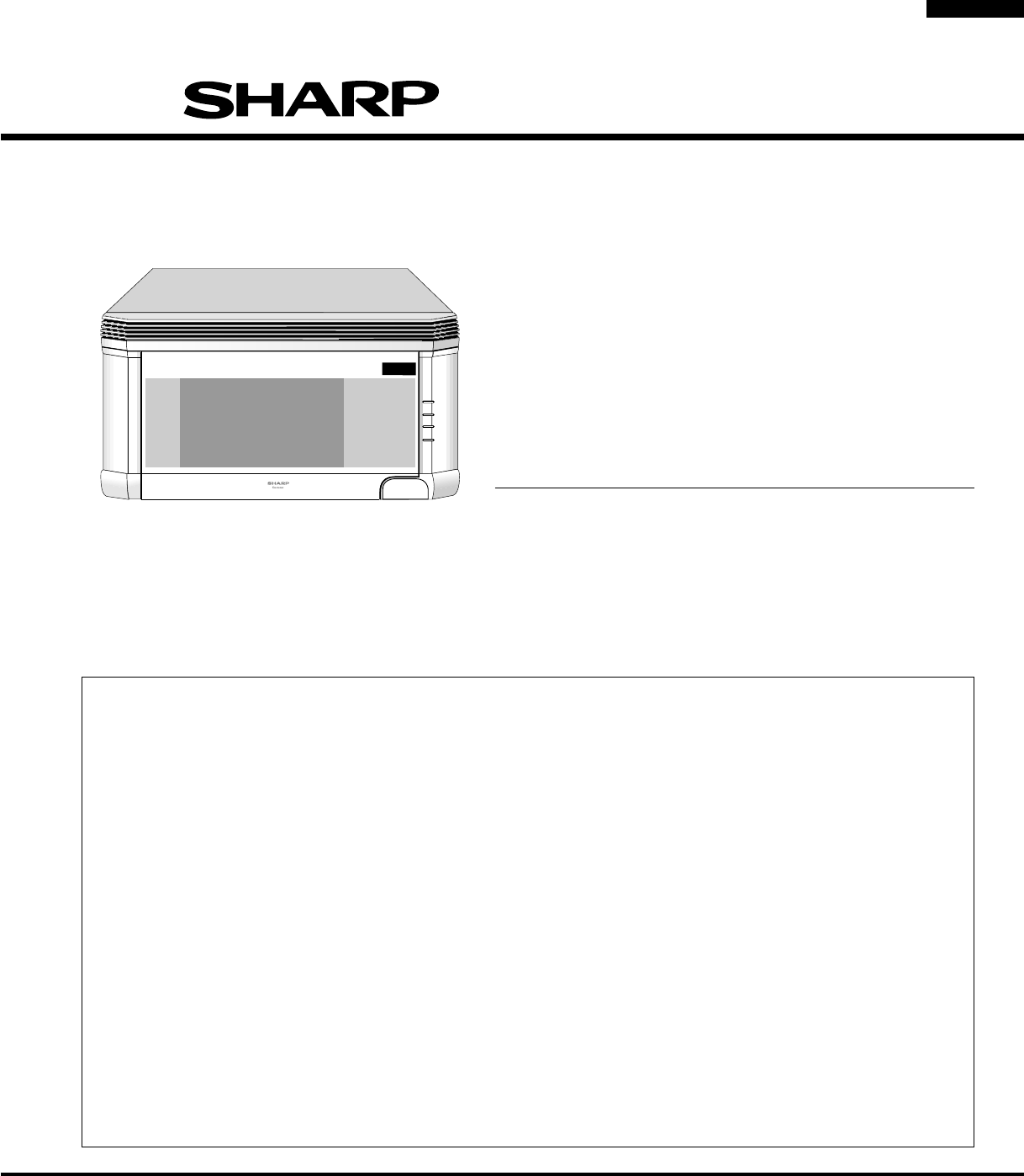
3R-1500R-1501R-1505R-1506SHARP ELECTRONICS CORPORATIONSHARP PLAZA, MAHWAH,NEW JERSEY 07430-2135SERVICE MANUALOVER THE RANGEMICROWAVE OVENR-1500/ R-150
4R-1500R-1501R-1505R-1506ITEM DESCRIPTIONPower Requirements 120 Volts / 14 Amperes60 HertzSingle phase, 3 wire groundedPower Output 1000 watts (IEC TE
5R-1500R-1501R-1505R-1506Electrical RequirementsThe oven is equipped with a 3-prong grounding plug. DO NOT UNDER ANY CIRCUMSTANCES CUT OR REMOVE THEGR
6R-1500R-1501R-1505R-15061000WATTSNO.LBS.OZ.CUPSCOOK DEFROSTKEEPWARMBAKEDPOTATOESFROZENVEGETABLESGROUNDMEATGROUNDMEATPOWERLEVELTIMERCLOCKPOULTRYBONELE
7R-1500R-1501R-1505R-1506OPERATIONDESCRIPTION OF OPERATING SEQUENCEThe following is a description of component functions duringoven operation.OFF COND
Powiązane produkty i podręczniki dla Kuchenki mikrofalowe Sharp PMP300
 (392 strony)
(40 strony)
(26 strony)
(392 strony)
(40 strony)
(26 strony)
© 2020, manymanuals.pl. Wszelkie prawa zastrzeżone. | 0.069 s |
 Manymanuals.com
 Manymanuals.de
 Manymanuals.fr
 Manymanuals.it
 Manymanuals.pl
 Manymanuals.cz
 Manymanuals.es
 Manymanuals-pt.com
Komentarze do niniejszej Instrukcji