Sharp XD250 Instrukcja Obsługi
Przeglądaj online lub pobierz Instrukcja Obsługi dla Kuchenki mikrofalowe Sharp XD250. R-1610 R-1611 R-1612 SUPPLEMENTAL SERVICE MANUAL [en] Instrukcja obsługi
- Strona / 28
- Spis treści
- ROZWIĄZYWANIE PROBLEMÓW
- BOOKMARKI
- SUPPLEMENTAL SERVICE MANUAL 1
- BEFORE SERVICING 2
- WARNING TO SERVICE PERSONNEL 3
- SERVICE MANUAL 5
- PRODUCT SPECIFICATION 6
- S e n s o r C o o k i n g 7
- More from your Microwave 7
- OPERATION 8
- TROUBLESHOOTING GUIDE 10
- TEST PROCEDURES 11
- TOUCH CONTROL PANEL ASSEMBLY 13
- DESCRIPTION OF LSI 14
- Output voltage 15
- WARNING FOR WIRING 16
- WARNING AGAINST HIGH VOLTAGE: 16
- CONTROL UNIT 18
- HIGH VOLTAGE COMPONENTS 18
- Figure S-3. LSI Unit Circuit 20
- Figure S-4. Indicator Circuit 21
- PARTS LIST 22
- MISCELLANEOUS 24
- SCREWS,NUTS AND WASHERS 24
- OVEN AND CABINET PARTS 25
- DOOR PARTS 26
- CONTROL PANEL PARTS 26
- Non-replaceable items 27
Podsumowanie treści
R-1610R-1611R-1612In the interest of user-safety the oven should be restored to its originalcondition and only parts identical to those specified shou
8R-1610R-1611R-1612TROUBLESHOOTING GUIDENever touch any part in the circuit with your hand or an uninsulated tool while the power supply is connected.
9R-1610R-1611R-1612TEST PROCEDURESPROCEDURELETTERCOMPONENT TESTM KEY UNIT TEST1. Disconnect the power supply cord, and then remove outer case.2. Open
10R-1610R-1611R-1612TEST PROCEDURESPROCEDURELETTERCOMPONENT TESTNOTE: ERROR will appear if the door is opened or STOP/CLEAR pad is touched during firs
11R-1610R-1611R-1612PlungerNCNOCOMCOMNONCR3 R4R1R2123F-1F-2F-3To connector (F)on Control Unit.CONNECTORTEST PROCEDURESPROCEDURELETTERCOMPONENT TESTSe
12R-1610R-1611R-1612DESCRIPTION OF LSILSI(IZA958DR)The I/O signal of the LSI(IZA958DR) is detailed in the following table.Pin No. Signal I/O Descripti
13R-1610R-1611R-1612(3) Detector Circuit of Absolute Humidity Sensor CircuitThis detector circuit is used to detect the output voltage ofthe absolute
14R-1610R-1611R-1612To prevent an electric shock, take the following pre-cautions.1. Before wiring,1) Disconnect the power supply cord.2) Open the doo
15R-1610R-1611R-161214.Remove the hood duct from the oven cavity by lifting it up.15.Screw the oven lamp off from the lamp socket.16.Remove the lamp s
16R-1610R-1611R-1612645123645123ABCDEFGHABCDEFGHFigure S-1. Pictorial DiagramHIGHVOLTAGERECTIFIERHIGH VOLTAGECAPACITORHIGH VOLTAGEWIRE AHIGH VOLTA
17R-1610R-1611R-1612645123645123ABCDEFGHABCDEFGHFigure S-2. Power Unit Circuit+–+–+–A 7C10C 2C 3C 1C 9C 4C11C 5C12C13C 6C 8C 7C14C15A 3A 5B 9NOCOMB 1B
R-1610R-1611R-1612PRECAUTIONS TO BE OBSERVED BEFORE ANDDURING SERVICING TO AVOID POSSIBLEEXPOSURE TO EXCESSIVE MICROWAVEENERGY(a) Do not operate or al
18R-1610R-1611R-1612645123645123ABCDEFGHABCDEFGHFigure S-3. LSI Unit CircuitC-4C-2INTGNDVCLEDVRTURNTABLEMOTOROVEN LAMPFAN MOTORHOOD LAMPHOOD MOTORH
19R-1610R-1611R-1612645123645123ABCDEFGHABCDEFGHFigure S-4. Indicator CircuitV CGNDIC1 P91IC1 P90IC1 P87IC1 P86IC1 P85IC1 P84IC1 P83IC1 P82IC1 P81IC1
20R-1610R-1611R-1612PARTS LISTNote: The parts marked “∆” may cause undue microwave exposure.The parts marked “*” are used in voltage more than 250V. &
21R-1610R-1611R-1612REF. NO. PART NO. § DESCRIPTION Q'TY CODERY1-2 RRLY-A113DRE0 M Relay (DU24D1-1PR(M)) 2 AGRY3-4 RRLY-B004MRE0 M Relay (FTR-F3A
22R-1610R-1611R-1612REF. NO. PART NO. § DESCRIPTION Q'TY CODEMISCELLANEOUS6- 1 CFZK-B131MRK0 M Installation material assembly 1 AM6-1-1 LBSHC004
23R-1610R-1611R-1612645123645123ABCDEFGHABCDEFGH4-11-127-32-12-54-134-192-67-47-36-107-57-37-17-101-161-137-81-174-177-37-97-94-151-107-114-91-101-97-
24R-1610R-1611R-1612645123645123ABCDEFGHABCDEFGH5-65-45-34-215-15-2-15-2-55-25-55-65-75-2-45-2-25-2-33-2-23-2-13-53-2-33-23-43-33-17-36-66-76-156-116-
25R-1610R-1611R-1612PACKING AND ACCESSORIESGREASE FILTER (x 2)6-13INSTALL MATERIAL ASSEMBLY6-16-26-3OPERATION MANUALWALL TEMPLATEINSTALLATION INSTRUCT
26R-1610R-1611R-1612'99 SHARP CORP. (5S2.530E) Printed in U.S.ACOPYRIGHT © 1999 BY SHARP CORPORATIONALL RIGHTS RESERVED.No part of this publicati
1R-1610R-1611R-1612WARNING TO SERVICE PERSONNELMicrowave ovens contain circuitry capable of pro-ducing very high voltage and current, contact withfoll
2R-1610R-1611R-1612MICROWAVE MEASUREMENT PROCEDUREA. Requirements:1) Microwave leakage limit (Power density limit): The power density of microwave rad
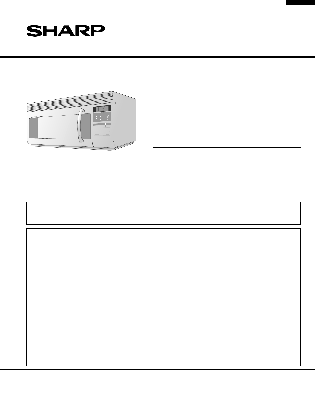
3R-1610R-1611R-1612SHARP ELECTRONICS CORPORATIONSHARP PLAZA, MAHWAH,NEW JERSEY 07430-2135SERVICE MANUALOVER THE RANGE MICROWAVE OVENR-1610/ R-1611/161
4R-1610R-1611R-1612ITEM DESCRIPTIONPower Requirements 120 Volts / 14 Amperes60 HertzSingle phase, 3 wire groundedPower Output 1000 watts (IEC-705 TEST
5R-1610R-1611R-1612GENERAL INFORMATIONGROUNDING INSTRUCTIONSThis oven is equipped with a three prong grounding plug. It must be plugged into a wall re
6R-1610R-1611R-1612OPERATIONDESCRIPTION OF OPERATING SEQUENCESENSOR COOKING CONDITIONUsing the Sensor Cooking function, the foods are cooked ordefrost
7R-1610R-1611R-1612SCHEMATICNOTE: CONDITION OF OVEN1. DOOR CLOSED2. COOKING TIME PROGRAMMED3. VARIABLE COOKING CONTROL "HIGH"4. "START&
Powiązane produkty i podręczniki dla Kuchenki mikrofalowe Sharp XD250
 (392 strony)
(40 strony)
(26 strony)
(392 strony)
(40 strony)
(26 strony)
© 2020, manymanuals.pl. Wszelkie prawa zastrzeżone. | 0.083 s |
 Manymanuals.com
 Manymanuals.de
 Manymanuals.fr
 Manymanuals.it
 Manymanuals.pl
 Manymanuals.cz
 Manymanuals.es
 Manymanuals-pt.com
Komentarze do niniejszej Instrukcji